Ships bow thrusters-Electric drives, diesel drives, hydraulic drives & white Gill type
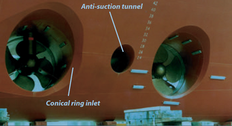
Bow thruster A lateral thruster fitted in an athwartships tunnel near the bow to improve
manoeuvrability. When the bow thruster is used while the vessel is moving forward
the thrust is partially counteracted by a vacuum created in the wake of the water jet
emanating from the thrusters. The effect is worst when the vessel is moving forward at
four to six knots. In such cases the vacuum on the hull can be relieved by the addition of
an anti-suction tunnel.
Bow thruster should be located as far forward as possible. Parallel side walls have favorable
influence. The suitable tunnel length: 2-3D. An attempt should be made to locate the propeller
in the midship plane. In short tunnels the propeller is located eccentrically on the port side, in
order to improve the thruster performance to starboard.
The average bow thruster power in ferries is 0.54kW/m2 (total bow thruster power/projected
windage area), varying up to 0.96 kW/m2. The tendency seems to be towards 0.6-0.8 kW/m2.
Stern thrusters seem to be dimensioned at 0.2-0.25 kW/m2.
Fig: WÄRTSILÄ BOW THRUSTER
The transverse thruster, installed in the bow and/or the stern, has become an
essential item of equipment on many vessels. It enables the normal process of
docking to be managed without tug assistance because the vessel is made more
manoeuvrable at low speeds.
Safety is increased when berthing in adverse
weather conditions provided that the required thruster capacity has been
correctly estimated. Transverse thrusters are installed to facilitate the
positioning of some types of workboats.
Some craft have thrust units for main
propulsion and azimuth thrusters with computer control for position holding.
Thrust calculations must be based on the above water profile of a ship as well
as the under water area. For passenger ships and ferries, the above water area
may be three times that of the under water lateral area. For loaded tankers and
bulk carriers, the situation is reversed but the unloaded profile must also be
considered.
The regular and frequent use of electrically driven bow thrust units on ferries
and other vessels operating on short sea routes means that motor windings are
kept dry by the heating effect of the current. This helps to maintain insulation
resistance.
There are potential problems with the electric motors and starters of
infrequently used units, particularly where installed in cold, forward bow thrust
compartments. They are subject to dampness through low temperature and
condensation. Insulation resistance is likely to suffer unless heaters are fitted in
the motor and starter casings. Space heaters may be fitted also.
A fan is
beneficial for ventilation before entry by personnel, but continuous delivery of
salt laden air could aggravate the difficulties with insulation resistance.
Bow thrust compartments below the waterline should be checked frequently
for water accumulation and pumped out as necessary to keep them dry.
Vertical ducts for drive shafts should also be examined for water and/or oil
accumulation. Flexible couplings with rubber elements quickly deteriorate if
operating in oily water. Thruster shaft seals must be inspected carefully during
preliminary filling of a drydock. Failure to detect and rectify leakage at this
stage can be expensive later.
Bow thrusters with diesel drive
By installing diesel drives various problems are avoided, for example the very
large power demand of electrically driven bow thrusters, the insulation
problems associated with the windings and the complications involved with
starting, speed control and reversing.
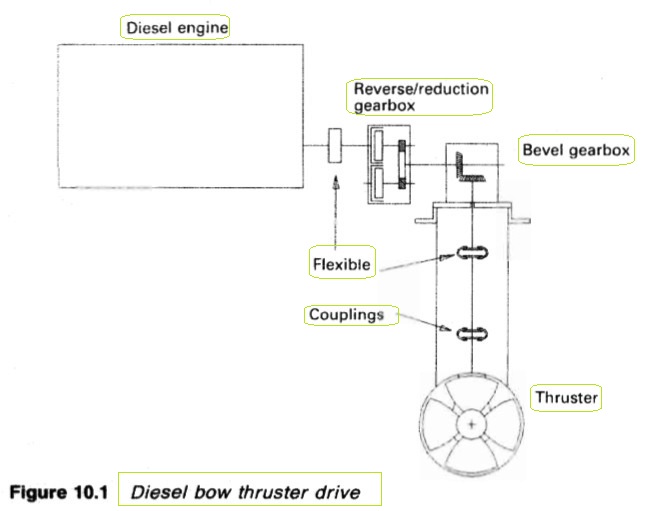
For a conventional thruster in an
athwartship tunnel, the diesel engine may be mounted at the same level as the
propeller to provide a direct drive through a reverse/reduction gear. An
alternative diesel arrangement (Figure 10.1) where space is limited, has the
diesel mounted above the thruster.
Both of the units shown, have horizontally
mounted diesel engines with simple speed control through the fuel rack, and a
reverse/reduction gearbox. The second arrangement requires an extra gearbox
with bevel gears to accommodate change of shaft line. Flexible couplings are
also fitted.
The reversing gearbox has ahead and astern clutches, with one casing
coupled to the diesel engine shaft and a drive to the other clutch casing,
through external gear teeth. The clutch casings rotate in opposite directions
and whichever is selected, will apply drive, ahead or astern, to the output shaft.
The engine idles when both clutches are disengaged.
Figure 10.1 : Diesel bow thruster drive
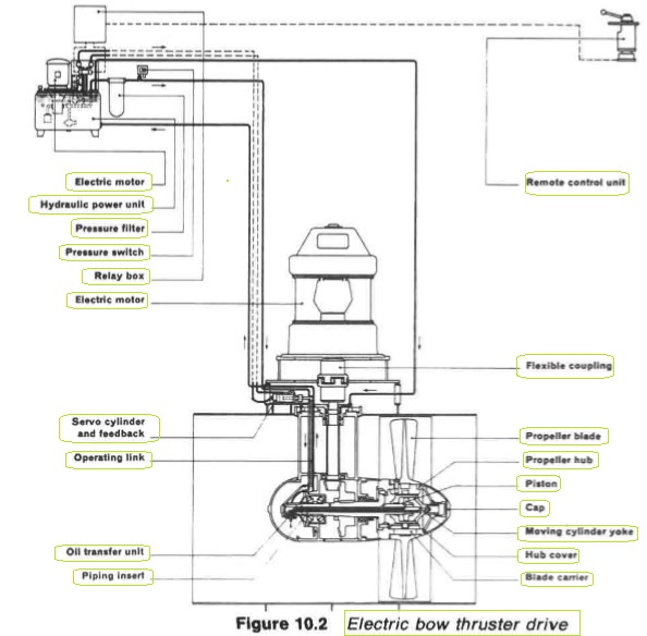
Alternating current electric motor drives with pitch control
An alternating current (a.c.) induction motor of the (squirrel) cage type is used
for many bow thrust units, with the motor being mounted above the
athwartships tunnel (Figure 10.2). Thrust is varied in direction and strength
through a controllable pitch propeller.
Figure 10.2 : Electric bow thruster drive
This arrangement permits the use of a simple and robust induction motor,
which operates at one speed. Starting current for a large induction motor tends
to rise to about eight times the normal full load figure and to reduce this a
star-delta or other low current starter is used. Low current starting implies low
starting torque as well. It is important that the hydraulic system is operative
and holding the propeller blades at neutral pitch when starting.
Pitch control for a thruster, is very similar to that for a controllable pitch
propeller. The shaft of the lips arrangement shown, is hollow and has a flange
to which the one-piece hub casting is held by bolts. The hub is filled with
lubricating oil and there is free flow from the hub to the pod through the
hollow shaft. The four blades are bolted to the blade carrier and have seals to
prevent oil leakage.
The pitch of the blades is altered by means of a sliding
block, fitted between a slot in the blade carrier and a pin on the moving cylinder
yoke. A piping insert in the hollow shaft connects the cylinder yoke to the oil
transfer unit which contains a servo valve for follow-up pitch control.
Fig: WÄRTSILÄ BOW THRUSTER CONTROLS
A
mechanical connection between the oil transfer unit and the inboard servo
cylinder facilitates accurate pitch settings and provides feedback for remote
control The hydraulic power unit is supplied with two safety valves, suction
and pressure filters, a pressure gauge and pressure switch, as well as an
electrically driven pump with a starter. To complete the equipment an electric
switch is supplied which, in combination with the pressure switch, prevents the
prime mover from starting when the pitch is in an off-zero position and/or no
hydraulic pressure is available.
Hydraulic thruster
An external hydraulic drive motor can be used as the alterative to an electric
motor but a design with the hydraulic unit within the bow thruster pod, was
produced by Stone Manganese electrically driven pump with a starter.
To complete the equipment an electric
switch is supplied which, in combination with the pressure switch, prevents the
prime mover from starting when the pitch is in an off-zero position and/or no
hydraulic pressure is available.
Hydraulic thruster
An external hydraulic drive motor can be used as the alterative to an electric
motor but a design with the hydraulic unit within the bow thruster pod, was
produced by Stone Manganese Marine. The variable displacement hydraulic
pump (Figure 10.3) is powered by a constant speed, uni-directional electric
motor or diesel prime mover connected through a flexible coupling.
Pump
output is controlled by means of a servo-control operated direct from the
bridge (or locally) to give the required speed and direction to the hydraulic
motor inside the thruster. The pod and propeller are suspended in a
conventional athwartship tunnel below the waterline.
Figure 10.3: Hydraulic drive bow thruster
1. Prime mover output shaft 6. Running lights 10. Hydraulic motor
2. Variable delivery pump 7. Propeller 11. End cover
3. Servo valve assembly 8. Fairing cover 12. Mounting plate
4. Bridge control unit 9. Main casing 13. Tacho generator
5. Thrust indicator
The White Gill type bow thruster unit for ship navigation
The customary transverse thruster has a limited application because it is based
in an athwartships tunnel. It cannot contribute to forward or reverse motion of
the ship and ship speed must be less than four knots for it to be effective. Some
schemes to improve performance have variously used double entry tunnels,
shallow vee or curved tunnels and different flap arrangements.
The White Gill type thruster which is fitted on a number of existing ships,
can provide thrust in any direction and is also used as the propulsion unit for
some small craft.
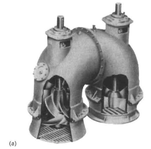
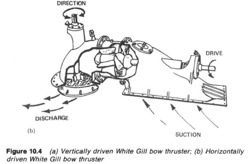
The White Gill type thruster
This type of thruster (Figure 10.4) is positioned at the bottom of the hull so that
the suction and discharge are at bottom shell plate level. Water is drawn in and
discharged by a propeller through static guide vanes, much as with an axial
pump. The guide vanes remove swirl and the water passes out as a jet through
a rotatable deflector. The latter can be turned through 360 deg.
The deflector has
curved vanes, resembling in section a turbine nozzle, which produces a near
horizontal jet of water. The deflector is rotated by a steering shaft which passes
through a gland in the casing. This in turn is controlled from the bridge. No
reverse arrangements are needed because thrust is available in any horizontal
direction. The drive for the propeller may be applied vertically (Figure 10.4a) or
horizontally (Figure 10.4b) depending on the design of unit installed.
(a) Vertically driven White Gill bow thruster;
Figure : (b) Horizontally
driven White Gill bow thruster
Summarized below ship stabilizing system detail guideline:
Safety is increased when berthing in adverse
weather conditions provided that the required thruster capacity has been
correctly estimated. Transverse thrusters are installed to facilitate the
positioning of some types of workboats.
More .....
The stabilizing power of fins is generated by their movement through the sea and lift' created by the flow of water above and below the 'aerofoil' or hydrofoil shape. When the front edge of the fin is tilted up, water flow across the top of the profile produces lift due to a drop in pressure while a lifting pressure is provided by flow along the underside.More.....
Housing and extending the fin is achieved by a double acting hydraulic
cylinder connected to the upper part of the trunnion. Power units, control and
sensing equipment are generally similar to other types of stabilizer except that
feed-back of fin angle is accomplished electrically by synchros.More....
Tank stabilizers (like bilge keels) are virtually independent of the forward speed
of the vessel. They generate anti-rolling forces by phased flow of appropriate
masses of fluid, usually water, in tanks installed at suitable heights and distances
from the ship's centre line.More....
General Cargo Ship.com provide information on cargo ships various machinery systems -handling procedures, on board safety measures and some basic knowledge of cargo ships that might be useful for people working on board and those who working in the terminal. For any remarks please
Contact us