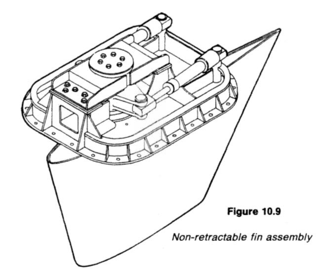
Figure : Non-retractable fin assembly
The angular velocity of roll of the ship causes the gyroscope to precess against centralizing springs to an amount proportional to the velocity and it generates a small force which is hydraulically amplified by a hydraulic relay unit to provide power sufficient to operate the controls of the variable delivery pump via suitable linkage. Part of the linkage is coupled to the fin shaft to transmit a cancelling signal to the pump control and to bring the fin to rest at the angle of tilt demanded by the sensing unit.
This type of control is often fitted in small installations, usually for economic reasons, and is most effective against resonant rolling. Ships seldom roll in a purely resonant mode; the sea state is often highly confused. More elaborate, and more expensive, control systems are required to deal with suddenly applied roll, rolling at periods off resonance and rolling in conditions arising from the combination of several wave frequencies.
A sensing unit based on a vertical-keeping gyroscope and a velocity gyroscope coupled into differentiating and summation units enables fin movement to be controlled by a composite function derived from roll angle, roll velocity and roll acceleration. By adding a 'natural list' unit, stabilization is achieved about the mean point of roll and so reduces both propulsion and stabilizing power demand. This is known as a compensated control system (Figure 10.10) and is generally used in large installations.
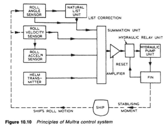
Figure : principles of multra control system
Roll reduction in excess of 90%, typically 30 deg out-to-out reduced to less than 3 deg out-to-out, can be achieved at resonance and low residual rolls can be maintained over a wide range of frequencies. However, since the stabilizing power varies as the square of the ship's speed, fins are least effective at low or zero speed where they function only as additional bilge keels.
Summarized below ship stabilizing system detail guideline:
- Ships bow thrusters-Electric drives, diesel drives, hydraulic drives & white Gill type
Safety is increased when berthing in adverse
weather conditions provided that the required thruster capacity has been
correctly estimated. Transverse thrusters are installed to facilitate the
positioning of some types of workboats.
More .....
- Fin stabilizers and stabilizing systems
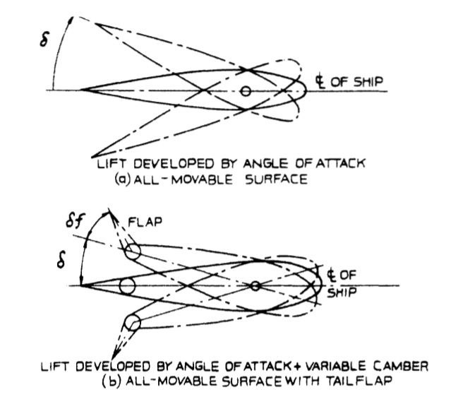
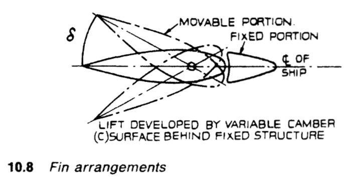
The stabilizing power of fins is generated by their movement through the sea and lift' created by the flow of water above and below the 'aerofoil' or hydrofoil shape. When the front edge of the fin is tilted up, water flow across the top of the profile produces lift due to a drop in pressure while a lifting pressure is provided by flow along the underside.More.....
- Folding fin stabilizer & Retractable fin stabilizers-
Housing and extending the fin is achieved by a double acting hydraulic
cylinder connected to the upper part of the trunnion. Power units, control and
sensing equipment are generally similar to other types of stabilizer except that
feed-back of fin angle is accomplished electrically by synchros.More....
- Tank stabilizers
Tank stabilizers (like bilge keels) are virtually independent of the forward speed
of the vessel. They generate anti-rolling forces by phased flow of appropriate
masses of fluid, usually water, in tanks installed at suitable heights and distances
from the ship's centre line.More....
Home page||
Cooling ||
Machinery||
Services ||
Valves ||
Pumps ||
Auxiliary Power ||
Propeller shaft ||
Steering gears ||
Ship stabilizers||
Refrigeration||
Air conditioning ||
Deck machinery||
Fire protection||
Ship design
||
Home ||
General Cargo Ship.com provide information on cargo ships various machinery systems -handling procedures, on board safety measures and some basic knowledge of cargo ships that might be useful for people working on board and those who working in the terminal. For any remarks please
Contact us
Copyright © 2010-2016 General Cargo Ship.com All rights reserved.
Terms and conditions of use
Read our privacy policy|| Home page||