
Home page||Cooling ||
Pressure governor for motor ships - Marine heat exchange process
What is Pressure governor ?
A discharge-pressure operated governor (Figure 1) and a rising head/capacity curve from full load to no load gives inherent stability of operation. The main feature of the governor is that if the pump loses suction the steam ports are opened wide, allowing the pump to accelerate rapidly to the speed at which the emergency trip acts.
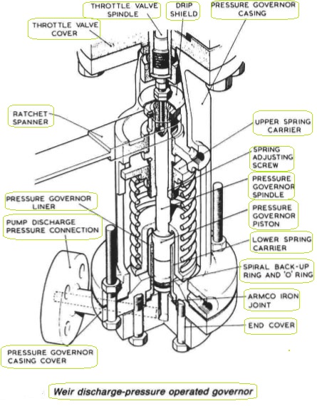
Figure 1: pressure governor
An adjusting screw, the collar of which bears against a platform in the casing, is threaded into the upper spring carrier and allows the compression of the spring to be altered by varying the distance between the upper and lower spring carriers. The piston, fitted with an O-ring and a spiral back-up ring, slides in a close fitting liner.
A flange on this liner locates in a recess in the governor casing cover and is sealed by an Armco iron joint ring. When the pump is started, the throttle valve moves upwards due to the increasing discharge pressure under the piston until the desired pressure is reached. At this point, the upward force exerted on the governor spindle by the piston is equal to that being applied downwards by the spring, and the throttle valve is admitting the correct quantity of steam to the turbine to maintain the desired discharge pressure.
With an increased demand on the pump the discharge pressure falls, allowing the pressure governor piston to move down under compulsion of the spring until the throttle valve opens to provide steam to satisfy the new demand. The reverse action takes place when the demand decreases.
Safety (overspeed) trip
The 'Bolt' type overspeed trip (Figure 2) consists essentially of a spring-loaded stainless steel bolt which, due to its special design, is heavier at one end than the other. The rotary motion of the turbine shaft tends to move the bolt outwards, while the spring retains it in its normal position until the turbine speed reaches a pre-determined safety level.
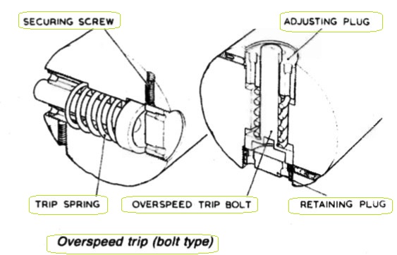
Figure 2: Overspeed trip bolt type
At this speed the centrifugal force exerted by the heavier end of the bolt overcomes the spring opposing it and the bolt moves outwards to strike the trip trigger. This in turn disengages the trip gear, allowing the steam stop valve to shut.
Turbine driven oil-lubricated pump
Prior to the introduction of the water lubricated turbo-feed pumps an oil-lubricated pump with a relatively long horizontal shaft was commonly used. In this particular pump the overspeed trip (Figure 3) was of the ring type. The pump was mounted on a taper at the end of the turbine shaft adjacent to the trip gear and was secured by a mild steel set bolt tapped into the end of the shaft. This set bolt was locked in place by a copper lock washer.
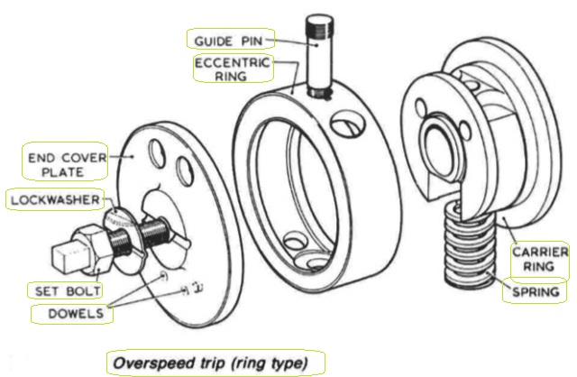
Figure 3: Overspeed trip ring type
The overspeed mechanism consisted of a case-hardened steel ring which, bored eccentrically, was weighted off-centre. The ring, however was spring loaded to maintain concentricity with the shaft until the speed of the turbine reached a predetermined safety limit. At that speed the centrifugal force exerted by the ring would overcome the force of the opposing spring and would then move outwards to strike the trip trigger.
Hydraulic balance mechanism
To control the axial movement of the rotating assembly, a balance piston (Figure 4) is arranged to counteract the effect of the thrust of the turbine and impellers. The arrangement keeps the rotating assembly in its correct position under all conditions of loading. Water at the approximate pressure of the pump discharge passes from the last stage of the pump between the impeller hub and the balance restriction bush C into the annular space B dropping in pressure as it does so.
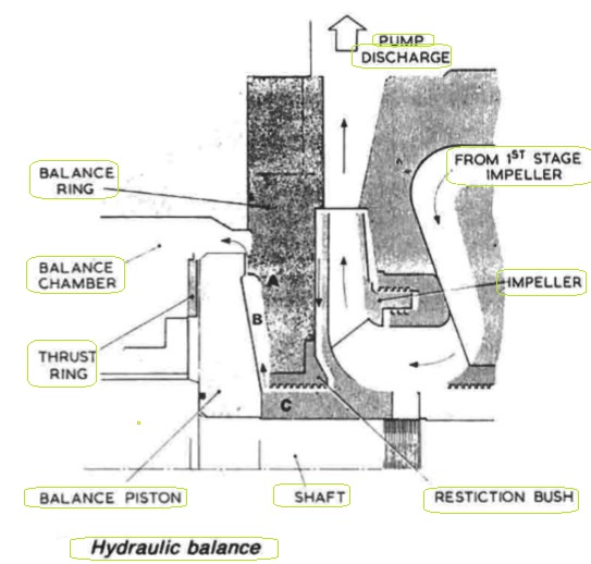
Figure 4: Hydraulic balance
The pressure of water in the chamber B tends to push the balance piston towards the turbine end. When the thrust on the balance piston overcomes the turbine and the impeller thrust, the gap A between the piston and balance ring widens and allows water to escape. This in turn has the effect of lowering the pressure in chamber B allowing the rotating assembly to move back towards the pump end.
Theoretically this cycle will be repeated with a smaller movement each time until the thrust on the balance piston exactly balances the other axial forces acting on the assembly. In practice the balancing of the forces is almost instantaneous and any axial movement of the shaft is negligible.
Summarized below various circulating systems for motorships, some of the basic procedure of heat exchangers & control of temperatures:
- Sea water circulation-systems
The usual arrangement for motorships has been to have sea-water circulation of coolers for lubricating oil, piston cooling, jacket water, charge air, turbo-charger oil (if there are sleeve type bearings) and fuel valve cooling, plus direct sea-water cooling for air compressors and evaporators....
-
Shell and tube heat exchangers for engine cooling water and lubricating oil cooling
Shell and tube heat exchangers for engine cooling water and lubricating oil cooling have traditionally been circulated with sea water. The sea water is in contact with the inside of the tubes, tube plates and water boxes....
-
Plate type heat exchanger
The obvious feature of plate type heat exchangers, is that they are easily opened for cleaning. The major advantage over tube type coolers, is that their higher efficiency is reflected in a smaller size for the same cooling capacity....
-
Details of charged air cooler
The charge air coolers fitted to reduce the temperature of air after the turbo-charger and before entry to the diesel engine cylinder, are provided with fins on the heat transfer surfaces to compensate for the relatively poor heat transfer properties of air....
-
Maintenance of heat exchangers
The only attention that marine heat exchangers should require is to ensure that the heat transfer surfaces should remain substantially clean and flow passage generally clear of obstructions. Indcation that fouling has occured is given by a progressive increase in the temperature difference between the two fluids, and change of pressure....
-
Central cooling system & Scoop arrangement for motorships
The corrosion and other problems associated with salt water circulation systems can be minimized by using it for cooling central coolers through which fresh water from a closed general cooling circuit is passed. The salt water passes through only one set of pumps, valves and filters and a short length of piping.....
-
Circulating systems for steamships
The main sea-water circulating system for a ship with main propulsion by steam turbine is similar to that of a motorship with a central cooling system. The difference is that the sea water passes through a ....
- Closed feed system and feed heating for motor ships
To ensure trouble-free operation of water-tube boilers the feed water must be of high quality with a minimal solid content and an absence of dissolved gases. Solids are deposited on the inside surfaces of steam generating tubes,....
- Marine condenser assembly
A condenser is a vessel in which a vapour is deprived of its latent heat of vaporization and so is changed to its liquid state, usually by cooling at constant pressure. In surface condensers, steam enters at an upper level, passes over tubes in which cold sea water circulates, falls as water to the bottom and is removed by a pump (or flows to a feed tank)....
-
Three stage air ejector with internal diffusers
A steam-jet ejector may be used to withdraw air and dissolved gases from the condenser. In each stage of the steam-jet ejector, high pressure steam is expanded in a convergent/divergent nozzle. ...
- Pressure governor for motor ships
The main feature of the governor is that if the pump loses suction the steam ports are opened wide, allowing the pump to accelerate rapidly to the speed at which the emergency trip acts....
- Liquid ring pump- Nash rotary liquid ring pumps
Nash rotary liquid ring pumps, in association with atmospheric air ejectors, may be used instead of diffuser-type steam ejectors and are arranged as shown...
- The Weir electro-feeder - a multi-stage centrifugal pump
A multi-stage centrifugal pump mounted on a common baseplate with its electric motor. The number of stages may vary from two to fourteen depending upon the capacity of the pump and the required discharge pressure....
- Feed water heaters for motor ships
Surface or direct contact feed heaters, play an important part in the recovery of latent heat from exhaust steam. Direct contact feed heaters are also known as de-aerators....
- Devaporizer & turbo-feed pump
If the de-aerator cannot be vented to atmosphere or to a gland condenser satisfactorily, a devaporizer is connected to the vapour outlet condensing the vapour vented with the non-condensable gases and cooling these gases before they are discharged. ...
- Typical de-aerator & Cascade trays
Normally, the de-aerator is mounted directly on a storage tank, into which the de-aerated water falls, to be withdrawn through a bottom connection by a pump or by gravity. The tank usually has a capacity....
Home page||Cooling ||Machinery||Services ||Valves ||Pumps ||Auxiliary Power ||Propeller shaft ||Steering gears ||Ship stabilizers||Refrigeration||Air conditioning ||Deck machinery||Fire protection||Ship design
||Home ||
General Cargo Ship.com provide information on cargo ships various machinery systems -handling procedures, on board safety measures and some basic knowledge of cargo ships that might be useful for people working on board and those who ashore. For any remarks please
Contact us
Copyright © 2010-2016 General Cargo Ship.com All rights reserved.
Terms and conditions of use
Read our privacy policy|| Home page||