Home page||Fire protection||
Halon system for Ship fire protection
Halon systems
Halons are included in the Montreal protocol as gases with ozone depletion
potential (ODP) and must not be specified for use in fixed fire fighting
installations. Compared with R12 which has been assigned an ODP of I, Halon
1211 has been given an ODP of 3 and Halon 1301 a figure of 10. Existing fixed
halon fire protection systems will need a replacement fire fighting medium for
which adaptations will be required.
Halon systems with Halon 1301 have been fitted to a large number of ships.
Halon is the name for halogenated compounds made by the replacement ot
hydrogen in methane or ethane with one of the halogens. Fluorine, chlorine
and bromine are halogens.
Halon 1301 has the chemical formula CF3 Br being known as bromo-trifluoromethane.
It is a colourless, odourless gas with a density five times that of air and
extinguishes fire by breaking the combustion chain reaction.
Other halogenated hydrocarbons such as methylbromide and carbon
tetrachioride have been used in the past as fire extinguishing agents but have
been banned by various authorities because of their extremely toxic nature.
Halon 1301 however, is classed by Underwriters Laboratories as least toxic'
(Group 6) and properly applied discharges of the gas allow people to see and
breathe permitting them to leave the fire area with some safety.
It must be pointed out however, that when Halon 1301 is exposed to flame
or hot surfaces above 480°C halogen acids and free halogens having a higher
level of toxicity are produced. A self- contained breathing apparatus or a fresh
air mask is therefore essential equipment when entering a space which has been
flooded with Halon 1301.
In some small machinery spaces Halon 1301 systems may be found in which
the Halon is stored in a sphere within the machinery space. In larger
installations the storage battery is similar to that used in CO2 systems. The gas
may be stored in 67 litre cylinders at a pressure of 40 bars. This equates to 75 kg
of Halon 1301.

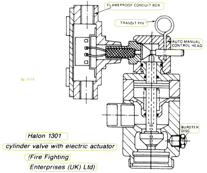
Figure : Halon 1301 cylinder valve with electric actuator (Fire Fighting
Enterprises (UK) Ltd)
Figure 14.18 shows the release gear used by Fire Fighting Enterprises (UK)
Ltd. In this system a cam on the end of the horizontal pin pushes the vertical
valve rod downwards, when the pin is actuated. The pin may be moved by a
pull wire or by one of a range of electrically or pneumatically operated actuators.
As soon as the valve rod opens the cylinder valve, gas from the cylinder is
admitted to the top side of the piston and holds the valve open. When the gas
pressure falls away a spring below the piston re-seats the valve. Only one
cylinder needs to be fitted with the horizontal pin, shown in the illustration.
The valves on the other cylinder can be linked to it with small bore copper pipe
so that gas from the master cylinder opens all of the other valves simultaneously.
Most halon cylinders are fitted with pressure gauges so that leakage can be
more readily detected. The cylinders are also fitted with bursting discs
Halon system operation
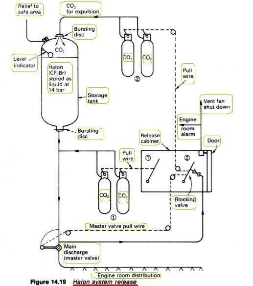
The halon release arrangement shown in Figure 14.19 consists of a storage
tank, two sets of CO2 operating cylinders and a manual release cabinet. The
halon is stored at a pressure of 14 bar in the holding tank, which has a pressure
relief, filling valve and level-indicator.
Release procedure is much the same as for COr When the cabinet is opened,
the alarm operates, fans stop and dampers or vent flaps will close. With all
entrances closed, the handles (1) and (2) are operated in succession. Handle (2)
can only be moved when released by the blocking mechanism.
The contents of the CO2 bottles opened by handle (1) pressurize the pipeline
between the halon tank and the master valve causing the bursting disc to
rupture and allowing the halon to flow as far as the master valve. The pressure
build up in this line acts on the blocking device to permit operation of handle
(2). The latter opens the master valve to the engine room distribution pipe and
also opens the CO2 bottles (2). CO2 from these ruptures the bursting disc at the
top of the storage tank and then assists in expelling the halon.
The discharge must be completed in 40 seconds but the alarm sounds as the
cabinet door is opened. Personnel must evacuate the space when warned. The
5% concentration gives a risk because the gas is toxic and must be treated with
the caution as CO2.

Figure : Halon system release
Portable halon extinguisher
The use of halon in portable extinguishers should be discontinued when suitable alternatives are available because of the high ozone depletion potential.
Summarized below general cargo ship fire protection equipments & guideline:
- Fire main system & related mechanism
The fire main
extends to the full length of the ship and from the machinery spaces to the
highest levels. Hydrants served by the main, are situated so that with suitable
hoses any area on the ship can be reached.
.....more
- CO2 fire extinguishing installation
Fire extinguishing installations employing CO2 stored under pressure at
ambient temperature are extensively used to protect ships' cargo compartments,
boiler rooms and machinery spaces. When released the CO2 is distributed
throughout the compartment, so diminishing the relative oxygen content and
rendering the atmosphere inert.
...... more
- Fire fighting equipments
Two independently powered pumps must be provided in all cargo ships of 1000 tons gross and over and in passenger ships of less than 4000 tons gross. Larger passenger vessels and passenger ferries must have three such pumps. The pumps are fitted with non-return valves if they are of the centrifugal type, to prevent loss of water back through open valves when not running.
..... more
- Details of fire detectors
A variety of devices are available for detecting fire in unmanned machinery
spaces but each has an ability to detect basically only one aspect. Thus, smoke
detectors based on the ionization chamber are able to recognize combustion
products but will not register radiation from a flame or heat.
.....more
- Machinery space fire & use of Walter Kidde CO2 system
Walter Kidde CO2 system employs pilot
CO2 cylinders to open the distribution system main stop valve and
subsequently the valves on the individual CO2 cylinders.
.....more
- Fire protection system for cargo holds
Holds for general cargo, have been protected against fire by fixed installations which deliver inert gas from an inert gas generator based on combustion of fuel (similar to the system available for inerting oil tankers) and halon systems.
.....more
- Low pressure CO2 storage
In some installations, the CO2 is stored in low pressure refrigerated tanks. The
cylindrical storage vessels are fabricated to the pressure vessel
requirements of the authorities. The tanks are of low temperature steel, fully
tested and stress relieved. They are mounted on supports designed to
withstand shock from collision.
..... more
- Halon system
Halon 1301 has the chemical formula CF3 Br being known as bromo-trifluoromethane.
It is a colourless, odourless gas with a density five times that of air and
extinguishes fire by breaking the combustion chain reaction.
.....more
- Multi-spray system for the machinery spaces
This system is similar to the sprinkler used in accommodation areas but the spray heads are not operated automatically. The section control valves (Figure 14.20) are opened by hand to supply water to the heads in one or more areas. Ready to use hoses can also be supplied. Fresh water is used for the initial charging and the system is brought to working pressure by means of the compressed air connection.
.....more
- Automatic sprinkler system
A network of
sprinkler heads is arranged throughout the spaces to be protected. Each sprinkler head is normally kept closed by a quartzoid bulb which is almost filled with a liquid having a high expansion ratio.
.....more
- Details various portable extinguishers & how to use ?
The first line of defence against fire in any area of the ship, is the portable fire extinguisher. Some common portable extinguishers that have been used at sea are described.
.....more
Home page||Cooling ||Machinery||Services ||Valves ||Pumps ||Auxiliary Power ||Propeller shaft ||Steering gears ||Ship stabilizers||Refrigeration||Air conditioning ||Deck machinery||Fire protection||Ship design
||Home ||
General Cargo Ship.com provide information on cargo ships various machinery systems -handling procedures, on board safety measures and some basic knowledge of cargo ships that might be useful for people working on board and those who working in the terminal. For any remarks please
Contact us
Copyright © 2010-2016 General Cargo Ship.com All rights reserved.
Terms and conditions of use
Read our privacy policy|| Home page||

