Home page||Fire protection||
Fire fighting equipments for general cargo ship
Fire pumps
Two independently powered pumps must be provided in all cargo ships of
1000 tons gross and over and in passenger ships of less than 4000 tons gross.
Larger passenger vessels and passenger ferries must have three such pumps.
The pumps are fitted with non-return valves if they are of the centrifugal type,
to prevent loss of water back through open valves when not running.
A relief
valve is necessary in the system if the pumps are capable of raising the pipeline
pressure so that it is greater than the design figure. With centrifugal pumps the
relief valve is unlikely to be needed but it is essential for a positive
displacement fire pump. Minimum line pressures and capacities are governed
by the regulations. Whilst fire pumps may be used for other duties such as
ballast or general service they should not normally be used for pumping oil.
Changeover arrangements may be fitted allowing a pump to be used for oily
bilge
Emergency fire pump
Normally, cargo vessels are provided with emergency fire pumps because a fire
in the engine room could put all of the other pumps out of action. Such a pump
is located away from the engine room in the
shaft tunnel, steering gear or in the forward part of the ship. The suction lift of
any pump is limited and for this reason emergency fire pumps are restricted to
being at a maximum of 6 m from the water level at light draught conditions.
Ideally they are installed below the waterline to guarantee avoidance of suction
problems. There have been difficulties in the past with some steering gear
located emergency fire pumps when the ship was in the ballast condition.
If the location of a centrifugal type emergency fire pump is the steering flat
then, because of the high suction lift involved, a priming pump is fitted. This
may be friction driven from the fire pump flywheel and once the fire pump is
running the priming pump drive wheel, normally held away from the flywheel
by a spring, must be held against it until the fire pump is primed. The fire pump
(centrifugal type) discharge valve is shut while the pump is being primed and
opened gradually as the suction is taken up.

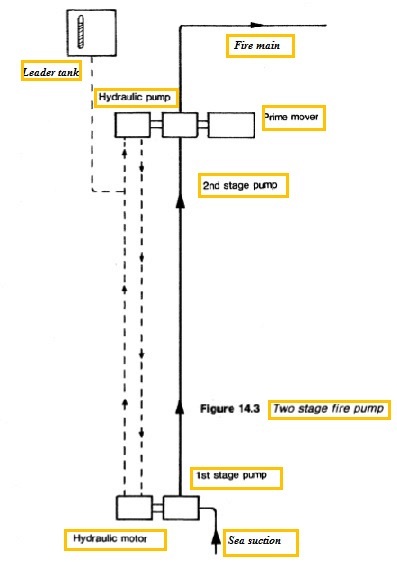
Figure : Two stage fire pump
On large vessels a special two stage pump arrangement may be used
(Figure 14.3) The first stage below the waterline is driven by a hydraulic motor.
The second stage and the hydraulic power unit are driven by a prime mover (or
electric motor from the emergency supply) which can be positioned at more
than the normal distance from the waterline.
If the fire pump is driven by a water-cooled diesel engine supplied with
cooling water from the fire pump a header tank will be provided to ensure that
the engine is cooled while the fire pump is being primed. The engine could
have a closed circuit fresh-water system, with the water being cooled in a
radiator. It is usual however, to fit an air-cooled diesel engine.
Where a closed-circuit fresh-water cooled engine is installed anti-freeze may
be needed for the radiator in cold weather.
An emergency pump has an independent diesel drive or some alternative
such as an electric motor powered from the emergency generator.
Pipelines
Where steel pipes are used, they are galvanized after bending and welding.
Their diameter is between 50 mm and 178 mm depending on the size and type
of ship. Engine room hydrants must have hoses and nozzles for jet and fog or
dual purpose nozzles.
International shore connection
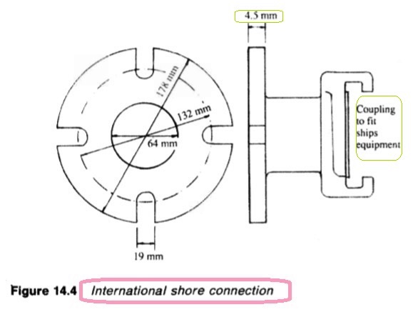
The international shore connection (Figure 14.4) is a standard sized flange with
nuts, bolts and washers and a coupling for the ship's fittings. The dimensions
are shown. The fitting and joint must be suitable for a working pressure of at
least 10.5 bar.
Four bolts are required of 16mm diameter and 50mm length, also eight
washers.

Figure : International shore connection
Hoses and nozzles
Fire hoses must be of approved materials. They are positioned adjacent to
hydrants together with suitable nozzles. Dual purpose nozzles can be adjusted
by rotation of the sleeve to produce a jet or spray. These are an alternative to
having available separate jet and spray or fog nozzles.
Foam adaptor
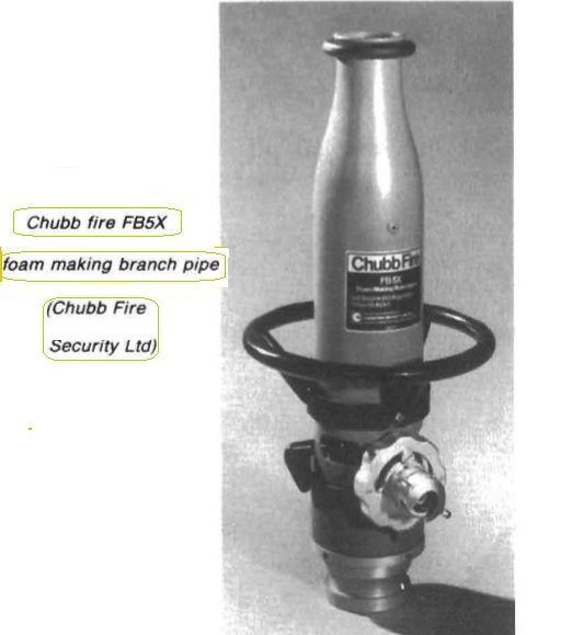
Foam branch pipes (Figure 14.5) which operate in a similar manner to those
used in deck installations for tankers, are fitted for use with the hydrants in
some machinery spaces and in particular for passenger ferry car decks. These
are available in various sizes for operation at a range of pressures and outputs.

Figure : Chubb fire FB5X foam making branch pipe (Chubb Fire
Security Ltd)
The foam branch pipe is connected through a hose to the hydrant and the water
flow produces a venturi effect which draws up the foam producing liquid
through the pick-up tube, from the container. The action also draws in air.
Mixing of the three components in the nozzle, causes formation of a jet of
foam. Initially, only water issues from the branch pipe and the nozzle is directed
away from the fire until foam appears. When the foam compound is exhausted,
water will again appear at the nozzle. Foam continuity is achieved by dropping
the pick-up tube in a bucket and keeping the bucket topped up with foam liquid,
Summarized below general cargo ship fire protection equipments & guideline:
- Fire main system & related mechanism
The fire main
extends to the full length of the ship and from the machinery spaces to the
highest levels. Hydrants served by the main, are situated so that with suitable
hoses any area on the ship can be reached.
.....more
- CO2 fire extinguishing installation
Fire extinguishing installations employing CO2 stored under pressure at
ambient temperature are extensively used to protect ships' cargo compartments,
boiler rooms and machinery spaces. When released the CO2 is distributed
throughout the compartment, so diminishing the relative oxygen content and
rendering the atmosphere inert.
...... more
- Fire fighting equipments
Two independently powered pumps must be provided in all cargo ships of 1000 tons gross and over and in passenger ships of less than 4000 tons gross. Larger passenger vessels and passenger ferries must have three such pumps. The pumps are fitted with non-return valves if they are of the centrifugal type, to prevent loss of water back through open valves when not running.
..... more
- Details of fire detectors
A variety of devices are available for detecting fire in unmanned machinery
spaces but each has an ability to detect basically only one aspect. Thus, smoke
detectors based on the ionization chamber are able to recognize combustion
products but will not register radiation from a flame or heat.
.....more
- Machinery space fire & use of Walter Kidde CO2 system
Walter Kidde CO2 system employs pilot
CO2 cylinders to open the distribution system main stop valve and
subsequently the valves on the individual CO2 cylinders.
.....more
- Fire protection system for cargo holds
Holds for general cargo, have been protected against fire by fixed installations which deliver inert gas from an inert gas generator based on combustion of fuel (similar to the system available for inerting oil tankers) and halon systems.
.....more
- Low pressure CO2 storage
In some installations, the CO2 is stored in low pressure refrigerated tanks. The
cylindrical storage vessels are fabricated to the pressure vessel
requirements of the authorities. The tanks are of low temperature steel, fully
tested and stress relieved. They are mounted on supports designed to
withstand shock from collision.
..... more
- Halon system
Halon 1301 has the chemical formula CF3 Br being known as bromo-trifluoromethane.
It is a colourless, odourless gas with a density five times that of air and
extinguishes fire by breaking the combustion chain reaction.
.....more
- Multi-spray system for the machinery spaces
This system is similar to the sprinkler used in accommodation areas but the spray heads are not operated automatically. The section control valves (Figure 14.20) are opened by hand to supply water to the heads in one or more areas. Ready to use hoses can also be supplied. Fresh water is used for the initial charging and the system is brought to working pressure by means of the compressed air connection.
.....more
- Automatic sprinkler system
A network of
sprinkler heads is arranged throughout the spaces to be protected. Each sprinkler head is normally kept closed by a quartzoid bulb which is almost filled with a liquid having a high expansion ratio.
.....more
- Details various portable extinguishers & how to use ?
The first line of defence against fire in any area of the ship, is the portable fire extinguisher. Some common portable extinguishers that have been used at sea are described.
.....more
Home page||Cooling ||Machinery||Services ||Valves ||Pumps ||Auxiliary Power ||Propeller shaft ||Steering gears ||Ship stabilizers||Refrigeration||Air conditioning ||Deck machinery||Fire protection||Ship design
||Home ||
General Cargo Ship.com provide information on cargo ships various machinery systems -handling procedures, on board safety measures and some basic knowledge of cargo ships that might be useful for people working on board and those who working in the terminal. For any remarks please
Contact us
Copyright © 2010-2016 General Cargo Ship.com All rights reserved.
Terms and conditions of use
Read our privacy policy|| Home page||


