
Home page||Deck machinery||
Powering deck machinery -
Systems and components
Pump and motor systems are used for powering deck machinery such as
winches and windlasses. Pump and actuating cylinders are normally employed
for hatch covers. One or more pumps will be used to supply the volume of fluid
at the pressure required to operate one or more motors. Pumps may be
classified into two groups:
1. those with a fixed delivery when running at a given speed;
2. those with a variable delivery at a given speed.
Fixed delivery pumps can have their constant output bypassed via control
valves until required or output can be matched to requirements by
incorporating a relief/accumulator, then stopping and starting, varying speed,
or connecting a variable delivery pump in parallel.
Variable delivery pump output can be controlled to give full flow in either
direction, and volume output can be varied from maximum down to zero.
Fixed delivery pumps
Constant output pumps of the gear or lobe type are precision
made to provide high pressure with minimum back leakage. The former
operate on the principle that as gears revolve, fluid is carried around the outside
between the gear teeth and the housing from the suction to the discharge side
of the pump.
Fluid from the discharge side is prevented from returning to the
intake side by the close meshing of the two gears and the small clearances
between the gears and housing. At the discharge side the fluid is discharged
partly by centrifugal effect and partly by being forced from between the teeth
as they mesh.
Gear pumps may be of the conventional kind or of the type with meshing
internal and external gears. Lobe pumps are a variation of
the latter.
Axial cylinder pumps can be made to deliver a fixed output by setting the
swash plate for continuous full stroke operation.
Variable delivery pumps
Variable delivery pumps are used in hydraulic installations as the means of
regulating pump output to suit demand. Steering gears are controlled directly
by varying the pump output and swash plate pumps are used to supply a range
of hydraulic deck machinery. Automatic stroke control can be used to adjust
the output.
Constant delivery pump systems
Hydraulic steering gears which are fitted with constant volume or fixed output
pumps may have a simple control valve arrangement which either delivers full
pump output to the steering gear or bypasses pump output completely.
System pressure rises sharply when oil is channelled to the gear. The fixed
output pumps of Woodward type hydraulic engine governors, supply to
accumulators, which maintain system pressure and hold a reserve of
operational oil against demand which may temporarily exceed pump capacity.
For general hydraulic systems where the pump delivers a constant volume
of oil, speed control of the hydraulic motor can be obtained by delivering the
required amount of oil to the motor through a control valve and diverting the
remainder through a bypass to the pump suction. The pump discharge pressure
is determined by the load. Speed and direction of rotation are controlled by a
lever operated balanced spool valve.
Unit type of circuit
The basic components of a hydraulic system of the Norwinch design are shown
in Figure 13.3. The pump in this case is of the vane type which consists of a
slightly elliptical case with a cylindrical rotor. The latter has radial slots
containing closely fitting rectangular vanes which are forced out against the
casing by centrifugal effect and oil pressure. As the rotor turns, the expanding
and contracting clearance between it and the casing produces a pumping
action. Both mechanical and magnetic filters and a relief valve are provided.
The expansion tank contains a reserve of oil.
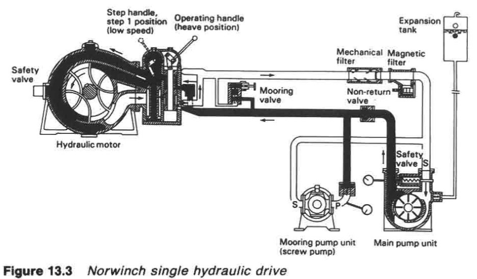
Figure : Norwinch single hydraulic drive
The hydraulic motor is also of the
vane type, with vanes mounted in a cylindrical rotor working in a housing
which incorporates two pressure chambers. When the motor is required to
exert maximum torque, oil flow from the pump is directed into both chambers.
For lighter loads an operating lever is actuated to direct the full flow to only
one of the pressure chambers. This system provides two variable speed ranges.
The system shown is for mooring winches which are self-tensioning.
Pumps for hydraulic installations, such as the one described, run at constant
speed and are driven by an electric motor or directly by a prime mover. With
the pump running there is a continuous flow of oil through the system whether
the motor is in operation or not. When the winch is not in use the oil merely
passes through the operating valve, bypassing the hydromotor and returns to
the pump.
Oil pressure is negligible when the hydromotor is idle, reducing power
required to a minimum. Oil in the pipelines to and from the motor always flows
in the same direction. At the motor controls the flow direction can be reversed
to change the rotation of the winch.
Many of the hydraulic systems, fitted to deck machinery are of the 'unit'
type, with one pump driving one motor, but there are great advantages to be
gained by the use of a ring main system. With the latter type of system, one
centrally located hydraulic pump is able to cater for the needs of a number of
auxiliaries which can work simultaneously or alternately at varying loads. As
the equipment powered from this central pumping installation need not be
restricted to deck machinery or to one type of equipment, the system offers
considerable savings on capital cost.
Variable displacement pump systems
The hydraulically operated steering gear with an axial piston (vsg type) or
radial piston (Hele-Shaw type) variable delivery pump, is an example of
variable displacement pump system. The pump itself controls the liquid flow to
move a ram or vane steering gear, so that operational control valves are not
required. The variable delivery pump is driven at constant speed by an a.c.
induction motor; the pump and motor being referred to in the regulations as a
power unit.
The rate of oil flow from the power unit controls the speed of
movement of the steering gear and rudder. A small movement of the telemotor
linkage puts the pump on part stroke and the gear moves through a small
distance, slowly. When a large movement of the rudder is required, the
telemotor linkage puts the pump on full stroke and initially the gear moves
rapidly to take the rudder to the desired angle. As the rudder moves, the
hunting gear gradually brings the pump control towards neutral, lessening the
pump stroke, so that the rate of movement reduces.
A variable displacement system can be used for deck machinery such as
windlasses, winches and capstans and also for cargo pumps. The power unit for
such circuit may be an axial piston (vsg type) pump with swash plate control to
maintain constant pressure in the system. To match the demand of the
hydraulic motors being supplied the swash plate control servo-motor monitors
system pressure and automatically adjusts pump output to keep pressure
constant. Oil cooling is provided by conventional sea-water circulated, tube
type heat exchangers.
System design
Careful system design and contamination control are required during
manufacture and installation of equipment. The number of joints and pipes are
kept to a minimum to reduce the possibility of leakage. Materials are selected
that will produce the least quantity of contaminating particles in the system.
Filters capable of taking out particles down to a specified size are necessary.
Shaft glands or seals must prevent leakage of oil from the machinery and they
must also keep contamination out whether the plant is running or shut down.
It is important with all hydraulic systems to ensure that interlocking
arrangements provided for pump or motor control levers are in the neutral
position before the pump driving motor can be started, in order to avoid
inadvertent running of unmanned machinery. Overload protection on
hydraulic systems is provided by use of the pressure relief valves set between
30-50% in excess of rated full load pressures.
Summarized below some of the basic operation of deck machinery and maintenance guide :
- Powering deck machinery -Systems and components
Pump and motor systems are used for powering deck machinery such as
winches and windlasses. Pump and actuating cylinders are normally employed
for hatch covers. One or more pumps will be used to supply the volume of fluid
at the pressure required to operate one or more motors.
......
- Mooring equipment for general cargo vessel
The operation of mooring a vessel has traditionally required the attendance of
a large number of deck crew fore and aft. Supervision of the moorings was also
necessary to maintain correct tension through changes due to the tides and the
loading or unloading of cargo.
......
- Hydraulic systems for deck machinery and cargo equipment
The three essential components for a hydraulic circuit, are the hydraulic fluid
held in a reservoir tank, a pump to force the liquid through the system and a
motor or cylinder actuator to convert the energy of the moving liquid into a
working rotary or linear mechanical force. Valves to control liquid flow and
pressure are required by some systems.
......
- General cargo ship deck machinery electric drives
Electric motors on vulnerable deck areas may be protected against ingress of
water by being totally enclosed in a watertight casing. Vents are provided on
some winches, which must be opened when the motor is operating in port.
......
- Handling deck machinery- Anchor windlasses,Anchor capstan & mooring winches
The windlass cablelifter brakes must be able to control the running anchor
and cable when the cablelifter is disconnected from the gearing when
letting go'. Average cable speeds vary between 5 and 7 m/s during this
operation.
......
- General cargo ship deck deck crane
A large number of ships are fitted with deck cranes. These require less time to
prepare for working cargo than derricks and have the advantage of being able
to accurately place (or spot) cargo in the hold. On container ships using ports
without special container handling facilities, cranes with special container
handling gear are essential.
......
- Mechanically operated steel hatch covers
Hatch cover equipment like the other deck machinery, has to exist in a very
hostile environment and the importance of regular maintenance cannot be
over-emphasized. Drive boxes and electrical enclosures should be checked
regularly for water-tightness.
......
- Derricks and cargo winches -Ship cargo handling gears
The duty of a deck winch is to lift and lower a load by means of a fixed rope on
a barrel, or by means of whipping the load on the warp ends, to top or luff the
derricks, and to warp the ship.
......
Home page||Cooling ||Machinery||Services ||Valves ||Pumps ||Auxiliary Power ||Propeller shaft ||Steering gears ||Ship stabilizers||Refrigeration||Air conditioning ||Deck machinery||Fire protection||Ship design
||Home ||
General Cargo Ship.com provide information on cargo ships various machinery systems -handling procedures, on board safety measures and some basic knowledge of cargo ships that might be useful for people working on board and those who working in the terminal. For any remarks please
Contact us
Copyright © 2010-2016 General Cargo Ship.com All rights reserved.
Terms and conditions of use
Read our privacy policy|| Home page||