
Home page||General service system ||
Bilge and ballast system layout - Ship service systems
Bilge system A piping system intended for disposing of water that may accumulate in
spaces within the vessel (holds, machinery spaces, cofferdams) due to condensation,
leakage, washing, fire fighting, etc. It is to be capable of controlling flooding in the
Engine Room as a result of limited damage to piping systems. However, the bilge
system is not able to cope with flooding resulting from a large hull damage not
protected in due time.
Bilge suctions Drain pipes placed on each side at the after end of the holds or compartments.
The suction end is fitted with a strainer or mud box. Bilge suctions in holds are to be
connected to the bilge main by branch lines.
Bilge system trials All elements of the bilge system are to be tested to demonstrate
satisfactory pumping operation, including emergency suctions and all controls. Upon
completion of the trials, the bilge strainers are to be opened, cleaned and closed up in
good order. According to ABS.
Bilge water The water that collects in the bilges of a vessel which generally becomes foul
and noxious. Bilge water also contains fluids from machinery spaces, internal drainage
systems, sludge tanks and various other sources. This mixture is collected in the bilge
water holding tank, which generally is maintained at an elevated temperature. Regardless of its source bilge water must be treated to reduce the oil content to levels meeting
international regulations for release into the environment.
Note: Cleaning agents, emulsifiers, solvents or surfactants used for cleaning purposes may
cause the bilge water to emulsify. Proper measures should be taken to minimize the presence
of these substances in the bilges of a ship.
In the system shown, (Figure below) the bilge main has suctions from the port and starboard sides of the engine room, from the tunnel well and from the different cargo holds. There are three pumps shown connected to the bilge main. These are the fire and bilge pump, the general service pump and the auxiliary bilge pump. These pumps also have direct bilge suctions to the engine room port side, starboard side and tunnel well respectively.
The ballast pump (port side for'd) could be connected to the bilge main but is shown with an emergency bilge suction only. The main sea-water circulating pump at the starboard side of the machinery space also has an emergency suction. This emergency suction or the one on the ballast pump is required by the regulations.
The ballast pump is self-priming and can serve as one of the required bilge pumps as well as being the stand-by sea-water circulating pump. The auxiliary bilge pump is the workhorse of the system and need not be one of the statutorily required bilge pumps. For this installation, it is a low capacity, smooth flow pump which is suited for use in conjunction with the oily/water separator.
All bilge suctions have screw down non-return valves with strainers or mud boxes at the bilge wells. Oily bilges and purifier sludge tanks have suitable connections for discharge to the oily water separator or ashore. The system is tailored to suit the particular ship. Vessels with open floors in the machinery space may have bilge suctions near the centre line and in such cases, wing suctions would not be necessary provided the rise of floor was sharp enough. The essential safety role of the bilge system means that bilge pumps must be capable of discharging directly overboard. This system is also used when washing down dry cargo spaces.
When clearing the water and oil which accumulates in machinery space bilges, the discharge overboard must be via the oily/water separator and usually with the use of the special bilge pump, i.e. the auxiliary bilge pump of the system shown.
Bilge water legislation Current MARPOL legislation stipulates that separated bilge water
containing 15 ppm or below in water can be disposed into international waters. Some
national, regional and local authorities have more stringent regulations. In the United
States and in the Baltic and North Seas disposal of separated bilge water is only permitted
at least 12 nautical miles from shore. In the future, legislation is expected to become
even more stringent, requiring levels of oil in water to be reduced further to five ppm for
discharge at sea and to zero-discharge in sensitive waters.
The following paragraphs are extracted from the International Convention for the Safety of Life at Sea 1974 Chapter 11-1 Regulation 18 which relates to passenger ships:
The arrangement of the bilge and ballast pumping system shall be such as to prevent the possibility of water passing from the sea and from water ballast spaces into the cargo and machinery spaces, or from one compartment to another. Special provision shall be made to prevent any deep tank having bilge and ballast connections being inadvertently run up from the sea when containing cargo, or pumped out through a bilge pipe when containing water ballast.
Provision shall be made to prevent the compartment served by any bilge suction pipe being flooded in the event of the pipe being severed, or otherwise damaged by collision or grounding in any other compartment. For this purpose, where the pipe is at any part situated nearer the side of the ship than one-fifth the breadth of the ship (measured at right angles to the centre line at the level of the deepest subdivision load line), or in a duct keel, a non-return valve shall be fitted to the pipe in the compartment containing the open end.
All the distribution boxes, cocks and valves in connection with the bilge pumping arrangements shall be in positions which are accessible at all times under ordinary circumstances. They shall be so arranged that, in the event of flooding, one of the bilge pumps may be operative on any compartment; in addition, damage to a pump or its pipe connecting to the bilge main outboard of a line drawn at one-fifth of the breadth of the ship shall not put the bilge system out of action.
If there is only one system of pipes common to all the pumps, the necessary cocks or valves for controlling the bilge suctions must be capable of being operated from above the bulkhead deck. Where in addition to the main bilge pumping system an emergency bilge pumping system is provided, it shall be independent of the main system and so arranged that a pump is capable of operating on any compartment under flooding condition; in that case only the cocks and valves necessary for the operation of the emergency system need be capable of being operated from above the bulkhead deck.
AH cocks and valves mentioned in the above paragraph of this Regulation which can be operated from above the bulkhead deck shall have their controls at their place of operation clearly marked and provided with means to indicate whether they are open or closed.

Figure : Bilge ballast fuel main
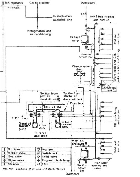
Figure : Bilge ballast fuel main
Cargo ships bilge pump procedure
Cargo ships have at least two
power driven bilge pumping units in the machinery space connected to the
main bilge line, and passenger ships have at least three.
In passenger ships the power driven bilge pumps are where practicable
placed in separate watertight compartments, so that all three are not
easily flooded by the same damage. Where the passenger ship has a length
in excess of 91.5 m it is a requirement that at least one of these pumps will
always be serviceable in reasonable damage situations. A submersible pump
may be supplied with its source of power above the bulkhead deck. Alternatively
the pumps are so distributed throughout the length of the ship that it
is inconceivable that one might not be able to work in the event of reasonable
damage.
Suction connections are led to each hold or compartment from the main
bilge line. Valves are introduced to prevent one watertight compartment
from being placed in direct communication with another, and to prevent
dry cargo spaces and machinery spaces being placed in direct communication
with tanks or pumps having sea inlets. These screw-down non-return
valves are often provided in a bilge valve distribution chest, or may be fitted
directly in the connections to the bilge main. The bilge pipes which are used
to drain cargo and machinery spaces are kept separate from the sea inlet
pipes and ballast pipes which are used for filling or emptying tanks where
the water and oil are carried. Often a separate dirty ballast system is arranged
to overcome this problem.
If possible the bilge pipes are kept out of the double bottom tanks, and in
way of a deep tank are led through a pipe tunnel. If the peaks are used as
tanks then a power pump suction is led to each peak. Only two pipes are
permitted to pass through the collision bulkhead below the bulkhead deck
and a screw-down valve operated from above the bulkhead deck is provided for each pipe in a chest on the forward side of the bulkhead.
An indicator is
provided to show at the valve operating position whether it is open or closed.
Bilge mains in passenger ships are kept within 20 per cent of the ships
beam of the side shell, and any piping outside this region or in a duct keel is
fitted with a non-return valve. These requirements are intended to prevent
any compartment from becoming flooded when the ship is grounded or
otherwise damaged and a bilge pipe is severed.
Many passenger ships are
provided with divided deep tanks or side tanks which permit cross flooding
arrangements limiting the list after a casualty. This cross flooding is
generally controlled by valves operated from above the bulkhead deck, but
self-acting arrangements can also be adopted.
Bilge and ballast piping may be of cast or wrought iron, steel, copper, or
other approved materials. Lead or other heat sensitive materials are not
permitted. The piping is fitted in lengths which are adequately supported
and have flanged connections, provision being made for expansion in each
range of pipes.
Summarized below some of the basic procedure of machinery service systems and equipment :
- Ballast arrangements
The ballasting of a vessel which is to proceed without cargo to the loading port is necessary for a safe voyage, sometimes in heavy weather conditions. On arrival at the port the large amount of ballast must be discharged rapidly in readiness for loading....
- Cargo ships bilge systems
The essential purpose of a bilge system, is to clear water from the ship's 'dry' compartments, in emergency. The major uses of the system, are for clearing water and oil which accumulates in machinery space bilges as the result of leakage or draining, and when washing down dry cargo holds. The bilge main in the engine room, has connections from dry cargo holds, tunnel and machinery spaces.....
- Bilge system layout details
All bilge suctions have screw down non-return valves with strainers or mud boxes at the bilge wells. Oily bilges and purifier sludge tanks have suitable connections for discharge to the oily water separator or ashore. The system is tailored to suit the particular ship......
- Domestic water system
Systems using gravity tanks to provide a head for domestic fresh and sanitary water, have long been superseded by schemes where supply pressure is maintained by a cushion of compressed air in the service tanks....
- Reverse osmosis
Osmosis is the term used to describe the natural migration of water from one side of a semi-permeable membrane into a solution on the other side. The
phenomenon occurs when moisture from the soil passes through the membrane covering of the roots of plants,....
- Salinometer features
The condensate or product, if of acceptable quality, is delivered to the appropriate tanks by the distilled water pump. Quality is continuously tested by the salinometer both at start up and during operation. If the device registers an excess of salinity it will dump the product and activate the alarm using its solenoid valves. The product is recirculated in some installations......
- Sewage systems
The exact amount of sewage and waste water flow generated on board ship is difficult to quantify. European designers tend to work on the basis of 70 litres/person/day of toilet waste (including flushing water) and about 130-150 litres/person/day of washing water (including baths, laundries, etc.). US authorities suggest that the flow from toilet discharges is as high as 114 litres/person/day with twice this amount of washing water......
- Sewage zero discharge system
A retention or holding tank is required where no discharge of treated or untreated sewage is allowed in a port area. The sewage is pumped out to shore reception facilities or overboard when the vessel is proceeding on passage at sea, usually beyond the 12 nautical mile limit. ...
- Biological sewage treatment
A number of biological sewage treatment plant types are in use at sea but nearly all work on what is called the extended aeration process. Basically this consists of oxygenating by bubbling air through or by agitating the surface. ....
- Sterilization system
Sterilization by the addition of chlorine, is recommended in Merchant Shipping Notice M1214. A later notice, M1401, states that the Electro-Katadyn process in use since the 1960s, has also been approved. Another problem with distilled water is that having none of the dissolved solids common in fresh water it tastes flat. It also tends to be slightly acidic due to its ready absorption of carbon dioxide (CO2). .....
- Treatment of water from shore
There is a risk that water supplied from ashore may contain harmful organisms which can multiply and infect drinking or washing water storage tanks. All water from ashore, whether for drinking or washing purposes, is to be sterilized. When chlorine is used, the dose must be such as to give a concentration of 0.2 ppm....
- Water production low pressure evaporator
A considerable amount of fresh water is consumed in a ship. The crew uses on average about 70 litre/person/day and in a passenger ship, consumption can be as high as 225 litre/person/day. Water used in the machinery spaces as make up for cooling system losses may be fresh or distilled but distilled water is essential for steam plant where there is a water tube boiler.
Steamship consumption for the propulsion plant and hotel services can be as high as 50 tonnes/day.....
- Flash evaporator system
The evaporator , boils sea water at the saturation temperature corresponding to the uniform pressure through the evaporation and condensing chambers. With flash evaporators the water is heated in one compartment before being released into a second chamber in which the pressure is substantially lower......
- Oil content monitor system
In the past, an inspection glass, fitted in the overboard discharge pipe of the oil/water separator permitted sighting of the flow. The discharge was illuminated by a light bulb fitted on the outside of the glass port opposite the viewer......
- Oily water separator
Oil/water separators are necessary aboard vessels to prevent the discharge of oil overboard mainly when pumping out bilges. They also find service when deballasting or when cleaning oil tanks. The requirement to fit such devices is the result of international legislation....
Home page||Cooling ||Machinery||Services ||Valves ||Pumps ||Auxiliary Power ||Propeller shaft ||Steering gears ||Ship stabilizers||Refrigeration||Air conditioning ||Deck machinery||Fire protection||Ship design
||Home ||
General Cargo Ship.com provide information on cargo ships various machinery systems -handling procedures, on board safety measures and some basic knowledge of cargo ships that might be useful for people working on board and those who working in the terminal. For any remarks please
Contact us
Copyright © 2010-2016 General Cargo Ship.com All rights reserved.
Terms and conditions of use
Read our privacy policy|| Home page||