marine engineering

Home page||General service system ||


Oil/water separators- working principles

Oil/water separators are necessary aboard vessels to prevent the discharge of oil overboard mainly when pumping out bilges. They also find service when deballasting or when cleaning oil tanks. The requirement to fit such devices is the result of international legislation.

Legislation was needed because free oil and oily emulsions discharged in a waterway can interfere with natural processes such as photosynthesis and re-aeration, and induce the destruction of the algae and plankton so essential to fish life. Inshore discharge of oil can cause damage to bird life and mass pollution of beaches.

Forces that contribute towards the total force available for oil and water separation are:

The force of gravity due to water and oil having different densities
oil will separate to the surface, water to the bottom
in the separator, heating coils, baffles, weirs and filters contribute towards separation.

sketch-oily-water-separator
Simple sketch of oily water separator

Sketch of shipboard oily water separator

The complete unit is filled with clean water and then the oil/water is pumped to the 1st stage coarse separating compartment. Here, oil having a lower density than water, will rise to the surface with heating coils aiding in this process. This is known as the collection space. A sensor will then sense the level of oil and it will be dumped accordingly via an oil valve to the dirty oil tank.

The remaining oil / water will move down to the fine separation compartment and move slowly between catch plates. More oil will separate on the underside of these plates and move outwards until free to rise up to the collection space. Almost oil free water then passes on to the 2nd stage of the unit. Here, two coalescer filters are situated, the first filter removes any physical impurities present and promotes some filtration, the second filter uses coalescer filter elements to achieve final filtration. Clean water then leaves the second stage on to a clean water holding tank or via a 15ppm monitor with audible and visual alarms overboard.

How oil density and temperature relate to ease of separation ? Oil density and temperature relate to the ease of separation because with added heat, the viscosity of the oil is reduced and so aids separation, plus the density of the oil will lower and allow for better separation.

Ships found discharging water containing more than 100 mg/litre of oil or discharging more than 60 litres of oil per nautical mile can be heavily fined, as also can the ship's Master.


In consequence it is important that an oil/water separator is correctly installed, used and maintained. It is generally accepted that oil is less dense than water and this is the basis of the design of devices to separate the two liquids.

Some of the modern heavy fuels however, have a density at 151C which approaches, is the same as or is even higher than that of water and this has added to the problems of separation in oil/water separators and in centrifuges. The operation of oil/water separators relies heavily on gravity and a conventional difference in densities. Centrifuges by their speed of rotation, exert a force many times that of gravitational effect and the heater reduces density in comparison with that of water.

Oil/water separators and centrifuges are both employed for the purpose of separating oil and water but there are major differences. Oil/water separators are required to handle large quantities of water from which usually, small amounts of oil must be removed. Various features are necessary to aid removal of the oil from the large bulk of water particularly when the difference in densities is small.

Centrifuges are required to remove (again usually) small quantities of water from a much larger amount of oil. Additionally the centrifuge must separate solids and it must, with respect to fuel, handle large quantities at the rate at which the fuel is consumed.

Principle of operation

The main principle of separation by which commercially available oil/water separators function, is the gravity differential between oil and water. In oily water mixtures, the oil exists as a collection of globules of various sizes. The force acting on such a globule, causing it to move in the water is proportional to the difference in weight between the oil particle and a particle of water of equal volume. This can be expressed as:

where: FS = separating force pw= density of water po = density of oil D = diameter of oil globule g — acceleration due to gravity.

The resistance to the movement of the globule depends on its size and the viscosity of the fluids. For small particles moving under streamline flow conditions, the relationship between these properties can be expressed by Stoke's Law: where: f. = resistance to movement jU = viscosity of fluid D = terminal velocity of particle d = diameter of particle.

When separation of an oil globule in water is taking place Fs will equal FT and the above equations can be worked to express the relationship of the terminal (or in this case rising) velocity of the globule with viscosity, relative density and particle size:

In general, a high rate of separation is encouraged by a large size of oil globule, elevated temperature of the system (which increases the specific gravity differential of the oil and water and reduces the viscosity of the oil) and the use of sea water.

Turbulence or agitation should be avoided since it causes mixing and re-entrainment of the oil. Laminar or streamlined flow is beneficial. In addition to the heating coils provided to optimize separation, there are various other means used to improve and speed up operation. The entrance area in oil/water separators is made large so that flow is slow and large slugs of oil can move to the surface quickly. (The low capacity pump encourages slow and laminar flow.) Alternation of flow path in a vertical direction continually brings oil near to the surface, where separation is enhanced by weirs which reduce liquid depth. Angled surfaces provide areas on which oil can accumulate and form globules, which then float upwards. Fine gauze screens are also used as coalescing or coagulating surfaces.

Pumping considerations

A faster rate of separation is obtained with large size oil globules or slugs and any break up of oil globules in the oily feed to the separator should be avoided. This factor can be seriously affected by the type and rating of the pump used, Tests were carried out by a British government research establishment some years ago on the suitability of various pumps for separator feed duties and the results were fairly good. It follows that equal care must be taken with pipe design and installation to avoid turbulence due to sharp bends or constrictions and to calculate correctly liquid flow and pipe size to guarantee laminar flow.

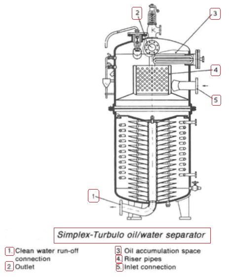
Simplex-Turbuto oil/water separator
Figure 1: Simplex-Turbuto oil/water separator

The Simplex-Turbulo oil/water separator

The Simplex-Turbulo oil/water separator (Figure 1 ) consists of a vertical cylindrical pressure vessel containing a number of inverted conical plates. The oily water enters the separator in the upper half of the unit and is directed downwards to the conical plates. Large globules of oil separate out in the upper part of the separator.

The smaller globules are carried by the water into the spaces between the plates. The rising velocity of the globules carries them upwards where they become trapped by the under-surfaces of the plates and coalesce until the enlarged globules have sufficient rising velocity to travel along the plate surface and break away at the periphery. The oil rises, is caught underneath an annular baffle and is then led up through the turbulent inlet area by risers to collect in the dome of the separator.

The water leaves the conical plate pack via a central pipe which is connected to a flange at the base of the separator, Two test cocks are provided to observe the depth of oil collected in the separator dome. When oil is seen at the lower test cock, the oil drain valve must be opened. An automatic air release valve is located in the separator dome. An electronically operated oil drainage valve is also frequently fitted. This works on an electric signal given be liquid level probes in the separator. Visual and audible oil overload indicators may also be fitted. To assist separation steam coils or electric heaters are fitted in the upper part of the separator. Where high viscosity oils are to be separated additional heating coils are installed in the lower part.

Before initial operation, the separator must be filled with clean water. To a large extent the conical plates are self-cleaning but periodically the top of the vessel should be removed and the plates examined for sludge build-up and corrosion. It is important that neither this separator nor any other type is run at over capacity.

When a separator is overloaded the flow becomes turbulent, causing re-entrainment of the oil and consequent deterioration of the effluent quality. To meet the requirement of legislation which came into force in October 1983 and which requires that the oil content of bilge discharges be reduced in general to 100 ppm and to 15 ppm in special areas and within 12 nautical miles of land, a second stage coalescer (Figure below) was added in some designs. Filter elements in the second stage remove any small droplets of oil in the discharge and cause them to be held until they form larger droplets (coalesce). As the larger globules form, they rise to the oil collecting space.
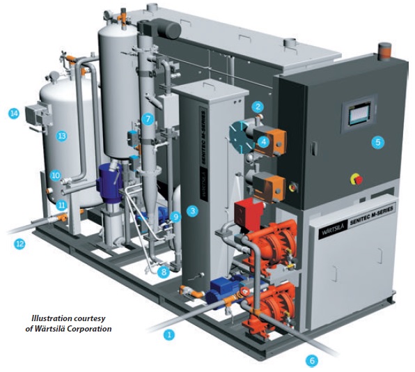


Oily water separator
Fig: Oily water separator WÄRTSILÄ SENITEC M1000, capacity 1 m3/hour

In fig Fig: Oily water separator WÄRTSILÄ SENITEC M1000, capacity 1 m3/hour. Principle component as below:
  1. Bilge water inlet
  2. Oil separation stage
  3. Emulsion tank
  4. Chemical dosing pumps
  5. Control panel
  6. Oil and solids effluent
  7. Chemical stage
  8. Dissolved air inlet
  9. Inlet to flotation stage
  10. Overboard
  11. Backwashing water outlet
  12. Fresh water inlet (to filter stage)
  13. Filter stage
  14. Oil monitor
Illustration courtesy of Wärtsilä Corporation


Summarized below some of the basic procedure of machinery service systems and equipment :
  1. Ballast arrangements

  2. The ballasting of a vessel which is to proceed without cargo to the loading port is necessary for a safe voyage, sometimes in heavy weather conditions. On arrival at the port the large amount of ballast must be discharged rapidly in readiness for loading....

  3. Cargo ships bilge systems

  4. The essential purpose of a bilge system, is to clear water from the ship's 'dry' compartments, in emergency. The major uses of the system, are for clearing water and oil which accumulates in machinery space bilges as the result of leakage or draining, and when washing down dry cargo holds. The bilge main in the engine room, has connections from dry cargo holds, tunnel and machinery spaces.....

  5. Bilge system layout details

  6. All bilge suctions have screw down non-return valves with strainers or mud boxes at the bilge wells. Oily bilges and purifier sludge tanks have suitable connections for discharge to the oily water separator or ashore. The system is tailored to suit the particular ship......

  7. Domestic water system

  8. Systems using gravity tanks to provide a head for domestic fresh and sanitary water, have long been superseded by schemes where supply pressure is maintained by a cushion of compressed air in the service tanks....

  9. Reverse osmosis

  10. Osmosis is the term used to describe the natural migration of water from one side of a semi-permeable membrane into a solution on the other side. The phenomenon occurs when moisture from the soil passes through the membrane covering of the roots of plants,....
  11. Salinometer features

  12. The condensate or product, if of acceptable quality, is delivered to the appropriate tanks by the distilled water pump. Quality is continuously tested by the salinometer both at start up and during operation. If the device registers an excess of salinity it will dump the product and activate the alarm using its solenoid valves. The product is recirculated in some installations......

  13. Sewage systems

  14. The exact amount of sewage and waste water flow generated on board ship is difficult to quantify. European designers tend to work on the basis of 70 litres/person/day of toilet waste (including flushing water) and about 130-150 litres/person/day of washing water (including baths, laundries, etc.). US authorities suggest that the flow from toilet discharges is as high as 114 litres/person/day with twice this amount of washing water......

  15. Sewage zero discharge system

  16. A retention or holding tank is required where no discharge of treated or untreated sewage is allowed in a port area. The sewage is pumped out to shore reception facilities or overboard when the vessel is proceeding on passage at sea, usually beyond the 12 nautical mile limit. ...

  17. Biological sewage treatment

  18. A number of biological sewage treatment plant types are in use at sea but nearly all work on what is called the extended aeration process. Basically this consists of oxygenating by bubbling air through or by agitating the surface. ....

  19. Sterilization system

  20. Sterilization by the addition of chlorine, is recommended in Merchant Shipping Notice M1214. A later notice, M1401, states that the Electro-Katadyn process in use since the 1960s, has also been approved. Another problem with distilled water is that having none of the dissolved solids common in fresh water it tastes flat. It also tends to be slightly acidic due to its ready absorption of carbon dioxide (CO2). .....

  21. Treatment of water from shore

  22. There is a risk that water supplied from ashore may contain harmful organisms which can multiply and infect drinking or washing water storage tanks. All water from ashore, whether for drinking or washing purposes, is to be sterilized. When chlorine is used, the dose must be such as to give a concentration of 0.2 ppm....

  23. Water production low pressure evaporator

  24. A considerable amount of fresh water is consumed in a ship. The crew uses on average about 70 litre/person/day and in a passenger ship, consumption can be as high as 225 litre/person/day. Water used in the machinery spaces as make up for cooling system losses may be fresh or distilled but distilled water is essential for steam plant where there is a water tube boiler. Steamship consumption for the propulsion plant and hotel services can be as high as 50 tonnes/day.....

  25. Flash evaporator system

  26. The evaporator , boils sea water at the saturation temperature corresponding to the uniform pressure through the evaporation and condensing chambers. With flash evaporators the water is heated in one compartment before being released into a second chamber in which the pressure is substantially lower......

  27. Oil content monitor system

  28. In the past, an inspection glass, fitted in the overboard discharge pipe of the oil/water separator permitted sighting of the flow. The discharge was illuminated by a light bulb fitted on the outside of the glass port opposite the viewer......

  29. Oily water separator

  30. Oil/water separators are necessary aboard vessels to prevent the discharge of oil overboard mainly when pumping out bilges. They also find service when deballasting or when cleaning oil tanks. The requirement to fit such devices is the result of international legislation....


Home page||Cooling ||Machinery||Services ||Valves ||Pumps ||Auxiliary Power ||Propeller shaft ||Steering gears ||Ship stabilizers||Refrigeration||Air conditioning ||Deck machinery||Fire protection||Ship design ||Home ||


General Cargo Ship.com provide information on cargo ships various machinery systems -handling procedures, on board safety measures and some basic knowledge of cargo ships that might be useful for people working on board and those who working in the terminal. For any remarks please Contact us


Copyright © 2010-2016 General Cargo Ship.com All rights reserved.
Terms and conditions of use
Read our privacy policy|| Home page||