
Home page||General service system ||
Bilge systems -Pumping and piping arrangements for modern cargo ships
All cargo ships are provided with pumping and piping arrangements so that
any watertight compartment or watertight section of a compartment can be
pumped out when the vessel has a list of up to 5°, and is on an even keel. In
the case of passenger ships, each compartment or section of a compartment
may be pumped out following a casualty under all practical conditions
whether the ship is listed or not.
The arrangements in the machinery space are such that this space may be
pumped out through two suctions under the above conditions. One suction
is from the main bilge line and the other from an independent power driven
pump. An emergency bilge suction is also provided in machinery spaces,
and may be connected to the main circulating water pump (for condenser)
in steam ships, or the main cooling water pump in motor ships.
In the construction of a merchant ship the shipbuilder is concerned with the
installation of the statutory bilge drainage, ballasting, general services, and
where required the liquid cargo loading and discharging, pumping and
piping arrangements. Piping arrangements may also be fitted in oil tankers
for tank washing and for introducing inert gas into the tanks.
Bilge Suctions
As the vessel is to be pumped out when listed it is
necessary to fit port and starboard suctions in other than very narrow
spaces. Generally vessels are designed to have a moderate trim by the stern
in service, and the suctions will therefore be placed in the after part of the
compartment. However, where a ship has a single hold which exceeds
33.5m in length suctions are also arranged in the forward half length of the
hold.
On many vessels a sloping margin plate is fitted and a natural bilge is
formed with the suctions conveniently located within this recess. Adequate
drainage to the bilge is provided where a ceiling covers this space.
If however
the tank top extends to the ship sides, bilge wells having a capacity of
at least 0.17m3, may be arranged in the wings of the compartment. In a
passenger ship these bilge wells must not extend to within 460mm of the
bottom shell so as to retain a reasonable margin of safety where the inner
bottom height is effectively reduced. The shaft tunnel of the ship is drained
by means of a well located at the after end, and the bilge suction is taken
from the main bilge line .
At the open ends of bilge suctions in holds and other compartments,
outside the machinery space and shaft tunnel, a strum box is provided. The
strum box is a perforated plate box welded to the mouth of the bilge line
which prevents debris being taken up by the bilge pump
suction.
Perforations in the strum box do not exceed 10 mm in diameter,
and their total cross-sectional area is at least twice that required for the
bore of the bilge pipe. Strums are arranged at a reasonable height above
the bottom of the bilge or drain well to allow a clear flow of water and to
permit easy cleaning. In the machinery space and shaft tunnel the pipe from
the bilges is led to the mud box which is accessible for regular cleaning. Each
mud box contains a mesh to collect sludge and foreign objects entering the
end of the pipe.
The essential purpose of a bilge system, is to clear water from the ship's 'dry' compartments, in emergency. The major uses of the system, are for clearing water and oil which accumulates in machinery space bilges as the result of leakage or draining, and when washing down dry cargo holds. The bilge main in the engine room, has connections from dry cargo holds, tunnel and machinery spaces.
Tanks for liquid cargo and ballast are served by cargo discharge systems and ballast systems respectively. They are not connected to the bilge system unless they have a double function, as for example with deep tanks that are used for dry cargo or ballast. Spectacle blanks or change over chests are fitted to connect/isolate spaces of this kind, as necessary. Accommodation spaces are served by scuppers with non-return valves which are fitted at the ship's side.
Bilge system regulations
Regulations prescribe the requirements for bilge systems and the details of a proposed arrangement must be submitted for approval to the appropriate government department or classification society. The number of power operated bilge pumps (usually three or four) that are required in the machinery spaces is governed by the size and type of ship.
For smaller vessels one of the pumps may be main engine driven but the other must be independently driven. A bilge ejector is acceptable as a substitute provided that, like the pumps, it is capable of giving an adequate flow rate. At least 120m/min (400ft/min) through the pipe is a figure that has been required. Pipe cross section is also governed by the rules, which means that this, combined with linear flow,
dictates a discharge rate.
Bilge ejectors are supplied with high pressure sea water from an associated pump. The diameters of bilge main and branch pipes, are found as stated above from formulae based on ship size and the Classification Societies generally prescribe the bore of the main bilge line and branch bilge lines and relate the bilge pump capacity of each pump to that required to maintain a minimum water speed in the line.
Fire pump capacity is related to the capacity of the bilge pump thus defined:
Bilge main dia. d1 = 1.68 JL(B + D) + 25 mm Branch dia. d2 - 2,16 ^/CCB + D) + 25 mm d2 not to be less than 50 mm and need not exceed 100 rnm. dl must never be less than d2
where
L = length of ship in m; B = breadth of ship in m; D= moulded depth at bulkhead deck in m; C = length of compartment in m.
Each pump should have sufficient capacity to give a water speed of 122 m/min through the Rule size mains of this bore.
Furthermore each bilge pump should have a capacity of not less than
The fire pumps, excluding any emergency fire pump fitted, must be capable of delivering a total quantity of water at a defined head not less than two-thirds of the total bilge pumping capacity. The defined head ranges from 3.2 bar in the case of passenger ships of 4000 tons gross or more to 2.4 bar for cargo ships of less than 1000 tons gross.
Pumps installed for bilge pumping duties must be self-priming or able to be primed. The centrifugal type with an air pump is suitable and there are a number of rotary self-priming pumps available. Engine driven pumps are usually of the reciprocating type and there are still in use many pumps of this kind driven by electric motors through cranks. The bilge pumps may be used for other duties such as general service, ballast and fire-fighting, which are intermittent.
The statutory bilge pumps may not be used for continuous operation on other services such as cooling, although bilge injections can be fitted on such pumps and are a requirement on main or stand-by circulating pumps. Common suction and discharge chests permit one pump to be used for bilge and ballast duties. The pipe systems for these services must, however, be separate and distinct.
The ballast piping has screw lift valves so as to be able to both fill and empty purpose-constructed tanks with sea water. The bilge system is designed to remove water or oily water from 'dry' spaces throughout the vessel and is fitted with screw-down non-return valves to prevent any
flooding back to the compartment served. The two could not be connected because they are incompatible. At the pump suction chest, the bilge valve must be of the screw down non-return type to prevent water from entering the bilge line from sea water or ballast suctions.
Materials which can be used are also given in the construction rules. When steel is used, it requires protection inside and out and both surfaces should be galvanized. The preparation of the surfaces for galvanizing is important as is the continuity of the coating.
The external painting of steel pipes may be the only protection used to prevent rust arising from contact with water in the bilges. Flanged joints are made between sections of pipe and support must be adequate. Branch, direct and emergency bilge suctions are provided to conform with the regulations and as made necessary by the machinery space arrangement.

Figure : Bilge ballast fuel main
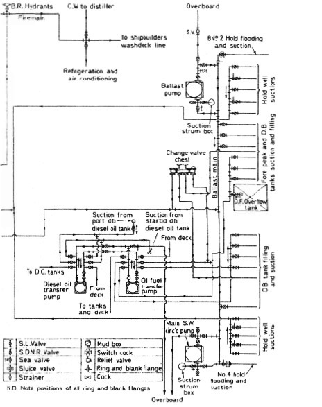
Figure : Bilge ballast fuel main
Summarized below some of the basic procedure of machinery service systems and equipment :
- Ballast arrangements
The ballasting of a vessel which is to proceed without cargo to the loading port is necessary for a safe voyage, sometimes in heavy weather conditions. On arrival at the port the large amount of ballast must be discharged rapidly in readiness for loading....
- Cargo ships bilge systems
The essential purpose of a bilge system, is to clear water from the ship's 'dry' compartments, in emergency. The major uses of the system, are for clearing water and oil which accumulates in machinery space bilges as the result of leakage or draining, and when washing down dry cargo holds. The bilge main in the engine room, has connections from dry cargo holds, tunnel and machinery spaces.....
- Bilge system layout details
All bilge suctions have screw down non-return valves with strainers or mud boxes at the bilge wells. Oily bilges and purifier sludge tanks have suitable connections for discharge to the oily water separator or ashore. The system is tailored to suit the particular ship......
- Domestic water system
Systems using gravity tanks to provide a head for domestic fresh and sanitary water, have long been superseded by schemes where supply pressure is maintained by a cushion of compressed air in the service tanks....
- Reverse osmosis
Osmosis is the term used to describe the natural migration of water from one side of a semi-permeable membrane into a solution on the other side. The
phenomenon occurs when moisture from the soil passes through the membrane covering of the roots of plants,....
- Salinometer features
The condensate or product, if of acceptable quality, is delivered to the appropriate tanks by the distilled water pump. Quality is continuously tested by the salinometer both at start up and during operation. If the device registers an excess of salinity it will dump the product and activate the alarm using its solenoid valves. The product is recirculated in some installations......
- Sewage systems
The exact amount of sewage and waste water flow generated on board ship is difficult to quantify. European designers tend to work on the basis of 70 litres/person/day of toilet waste (including flushing water) and about 130-150 litres/person/day of washing water (including baths, laundries, etc.). US authorities suggest that the flow from toilet discharges is as high as 114 litres/person/day with twice this amount of washing water......
- Sewage zero discharge system
A retention or holding tank is required where no discharge of treated or untreated sewage is allowed in a port area. The sewage is pumped out to shore reception facilities or overboard when the vessel is proceeding on passage at sea, usually beyond the 12 nautical mile limit. ...
- Biological sewage treatment
A number of biological sewage treatment plant types are in use at sea but nearly all work on what is called the extended aeration process. Basically this consists of oxygenating by bubbling air through or by agitating the surface. ....
- Sterilization system
Sterilization by the addition of chlorine, is recommended in Merchant Shipping Notice M1214. A later notice, M1401, states that the Electro-Katadyn process in use since the 1960s, has also been approved. Another problem with distilled water is that having none of the dissolved solids common in fresh water it tastes flat. It also tends to be slightly acidic due to its ready absorption of carbon dioxide (CO2). .....
- Treatment of water from shore
There is a risk that water supplied from ashore may contain harmful organisms which can multiply and infect drinking or washing water storage tanks. All water from ashore, whether for drinking or washing purposes, is to be sterilized. When chlorine is used, the dose must be such as to give a concentration of 0.2 ppm....
- Water production low pressure evaporator
A considerable amount of fresh water is consumed in a ship. The crew uses on average about 70 litre/person/day and in a passenger ship, consumption can be as high as 225 litre/person/day. Water used in the machinery spaces as make up for cooling system losses may be fresh or distilled but distilled water is essential for steam plant where there is a water tube boiler.
Steamship consumption for the propulsion plant and hotel services can be as high as 50 tonnes/day.....
- Flash evaporator system
The evaporator , boils sea water at the saturation temperature corresponding to the uniform pressure through the evaporation and condensing chambers. With flash evaporators the water is heated in one compartment before being released into a second chamber in which the pressure is substantially lower......
- Oil content monitor system
In the past, an inspection glass, fitted in the overboard discharge pipe of the oil/water separator permitted sighting of the flow. The discharge was illuminated by a light bulb fitted on the outside of the glass port opposite the viewer......
- Oily water separator
Oil/water separators are necessary aboard vessels to prevent the discharge of oil overboard mainly when pumping out bilges. They also find service when deballasting or when cleaning oil tanks. The requirement to fit such devices is the result of international legislation....
Home page||Cooling ||Machinery||Services ||Valves ||Pumps ||Auxiliary Power ||Propeller shaft ||Steering gears ||Ship stabilizers||Refrigeration||Air conditioning ||Deck machinery||Fire protection||Ship design
||Home ||
General Cargo Ship.com provide information on cargo ships various machinery systems -handling procedures, on board safety measures and some basic knowledge of cargo ships that might be useful for people working on board and those who working in the terminal. For any remarks please
Contact us
Copyright © 2010-2016 General Cargo Ship.com All rights reserved.
Terms and conditions of use
Read our privacy policy|| Home page||