Home page||Refrigeration system||
Container cooling systems for cargo ships
Container cooling
Refrigerated containers is used to preserve perishable foodstuffs during
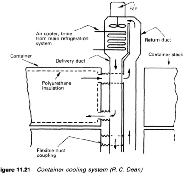
transport or storage. Container cooling systems designed for the cooling of refrigerated containers employ trunkings (Figure 11.21) arranged so that containers stowed in stacks between built-in
guide rails, can be connected to the suction and delivery air ducts of the ship's refrigeration plant by bellows pieces operated pneumatically.
The air is cooled either by brine or direct expansion batteries and the containers are arranged so that one cooler can maintain a stack of containers at a given temperature. The temperature of the return air duct for each container is monitored.
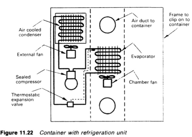
Provision of a cooler and trunking system for maintaining container temperatures must also be provided at container terminals. Individual containers with their own refrigeration plant (Figure 11.22) are connected to the 440 or 220 a.c. sockets provided on deck. These containers may be arranged for ships' systems with either 440 or 220 V by provision of a direct connection for a 220 V supply to the self-contained refrigerator and a 440V connection through a step down transformer.

Figure : Container cooling system (R. C. Dean)

Figure :Container with refrigeration unit
Air cooler fans
Fans may be either centrifugal or of the propeller type; the air circulation systems being based on a pressure requirement of about 50 mm W.G. (water gauge). All of the electrical energy of the fan motors is dissipated in the form of heat and has to be removed by the refrigerating plant.
Fan output should be variable so that it can be reduced as heat load diminishes. There was no problem with d.c. motors but with a.c. either the motors are two speed, or each cooler has a number of fixed speed fans which can be switched off individually to suit the load. In the latter case, provision must be made to blank off the stopped fans to prevent air loss. The capacity of the fans is determined by the number of air changes per hour required in the cargo chambers, and this is influenced by the maximum calculated heat load.
In a system using air coolers and fans, all the heat load must be carried away by the circulating air and the difference between delivery and suction air temperatures is directly proportional to the weight of air being circulated. Since the temperature difference is limited by the allowable temperature spread in the cargo chambers and maximum temperature spread in the cargo chambers and maximum load can be estimated, the selection of suitable fans is straightforward. In most installations the number of air changes required per hour, based on an empty chamber, varies between 40 for dead cargoes such as frozen meat or fish and 80 for fruit cargoes, such as bananas which evolve heat freely.
Summarized below various refrigeration system components, working process and maintenance guideline:
- Automatic direct expansion refrigeration- vapour compression
The basic components of any refrigeration system (Figure 11.1) working on the
vapour compression cycle, are the compressor, condenser, expansion valve,
evaporator and the refrigerant fluid which is alternately vaporized and liquefied
during the refrigeration cycle. The temperature at which a fluid boils or
condenses, is known as the saturation temperature and varies with pressure....more
-
Choice of refrigerants
Theoretically, almost any liquid can be used as a refrigerant if its pressure/temperature relationship is suitable for the conditions. Although no perfect refrigerant is known, there are certain factors which determine a refrigerant's desirability for a particular duty and the one selected should possess as many as possible of the following
characteristics.....more
-
Refrigeration systems - Chamber cooling arrangements
To avoid having an extended refrigeration circuit for cargo cooling, a brine system can be used. The brine is cooled by the evaporator and in turn cools grids or batteries. Grids provide cooling which relies on convection and conduction but air circulated through brine batteries provides a positive through cooling effect.
.....more
-
Refrigeration system components
Marine condensers are generally of the shell and tube type, designed for high pressures. There may a few coil-in-casing or other types still in use. The coolant passes through the tubes with refrigerant condensing on the outside......more
-
Refrigeration system compressors
Refrigeration compressors are usually either reciprocating, or of the rotary
screw displacement type. Centrifugal and rotary vane compressors have also
been used.....more
-
Refrigeration systems expansion valves
The expansion valve is the regulator through which the refrigerant passes from the high pressure side of the system to the low pressure side. The pressure drop causes the evaporating temperature of the refrigerant to fall below that of the evaporator. .....more
- Monitoring instruments,CO2 measurement & Heat leakage and insulation test
All necessary cargo temperature readings are obtained on modern reefers and container ships on a data logger which makes an automatic record. The temperatures and pressures relating to refrigerant gas and liquid, cooling water, brine and the ambient are also required. Most of these are obtained from direct reading instruments.
.....more
- Marine condenser assembly
The temperature of the refrigerated spaces with a direct expansion system is controlled between limits through a thermostatic switch and a solenoid valve which is either fully open to permit flow of refrigerant to the room evaporator, or closed to shut off flow. The solenoid valve is opened when the sleeve moving upwards due to the magnetic coil hits the valve spindle tee piece and taps the valve open.....more
- Comparison between refrigerants R717 ammonia & R744 carbon dioxide
The ammonia used for refrigeration systems based on the use of a compressor,
condenser, expansion valve and an evaporator (Figure 11.2) is dry (anhydrous)
in that there is no water in solution with it. It has the chemical formula NH3 but
as a refrigerant, it is coded with the number R717....more
-
Container cooling system
The air is cooled either by brine or direct expansion batteries and the containers are arranged so that one cooler can maintain a stack of containers at a given temperature. The temperature of the return air duct for each container is monitored.....more
Home page||Cooling ||Machinery||Services ||Valves ||Pumps ||Auxiliary Power ||Propeller shaft ||Steering gears ||Ship stabilizers||Refrigeration||Air conditioning ||Deck machinery||Fire protection||Ship design
||Home ||
General Cargo Ship.com provide information on cargo ships various machinery systems -handling procedures, on board safety measures and some basic knowledge of cargo ships that might be useful for people working on board and those who working in the terminal. For any remarks please
Contact us
Copyright © 2010-2016 General Cargo Ship.com All rights reserved.
Terms and conditions of use
Read our privacy policy|| Home page||

