Home page||Refrigeration system||
Refrigeration system-Condensers,Evaporators,float valves,HP cut-outs & other components
Condensers
Marine condensers are generally of the shell and tube type, designed for high pressures. There may a few coil-in-casing or other types still in use. The coolant passes through the tubes with refrigerant condensing on the outside. Condenser tubes provide heat transfer surfaces in which heat from the hot refrigerant on the outsides of the tubes passes through the walls of the tubes to the cooling water inside. Sea water is the usual cooling medium for shell and tube condensers, but fresh water from central cooling systems is increasingly being used. The refrigerant vapour is cooled first to saturation point, then to the liquid state.
The design of condensers is largely dictated by the quantity and cost of the circulating water, and, where water is plentiful as at sea, a large number of short circuits may be used, to keep pressure drop to a minimum. Water velocity is restricted to prevent erosion of the tubes, usually being kept below 2.5 m/s.

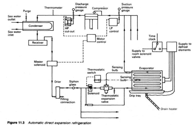
Figure : Automatic direct expansion refrigeration
Marine condensers are very susceptible to corrosion and much research has been done to lengthen their useful life. With halogenated hydrocarbon refrigerants, the use of aluminium brass or cupro-nickel tubes and brass tube plates is acceptable and has reduced the rate of corrosion on the sea-water side.
Refrigerant 717 (ammonia) tends to corrode these materials however, and it has been found necessary to use stainless steel or even bimetallic tubes and clad tube plates, with ferrous metal being in contact with the refrigerant, and non-ferrous with the sea water. The use of sacrificial anodes in the water ends of the condensers is common and sometimes a short length of ungalvanized pipe is fitted between the condenser and the galvanized steel pipe system.
The use of fresh water from a central cooling system closed circuit, avoids the problem of sea-water corrosion.
Evaporators
In the direct expansion system, shown in Figure 11,3, evaporation takes place in air coolers consisting of pipe grids, plain or finned, enclosed in a closely fitting casing, through which air from the holds or chambers is circulated by forced or induced draught fans. This type of evaporator can be operated either partly flooded, fully flooded, with incorporated accumulators, or dry.
In the latter, the refrigerant flow is controlled at the expansion valve in such a way that, as it passes through the grids, it is completely vaporized and slightly superheated. Where brine is used as the secondary refrigerant, evaporators may be of the shell and tube type.
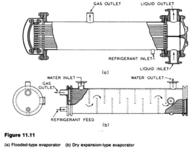
In a shell and tube evaporator, the area of tube surface in contact with the liquid refrigerant determines its performance. The brine to be cooled may be circulated through the tubes with the refrigerant being on the outside of them. This involves either a high liquid level in the shell, or the placing of the tubes in the lower part of the shell only, the upper part then forming a vapour chamber. Modern flooded evaporators incorporate finned tubes. Shell and tube evaporators (Figure 11.11) may also be of the dry expansion type, in which the refrigerant passes through the tubes, and the brine is circulated through the shell. The advantages of this type are a smaller refrigerant charge and a more positive return of lubricating oil to the compressor.

Figure : (a) Flooded-type evaporator (b) Dry expansion-type evaporator
Expansion valves
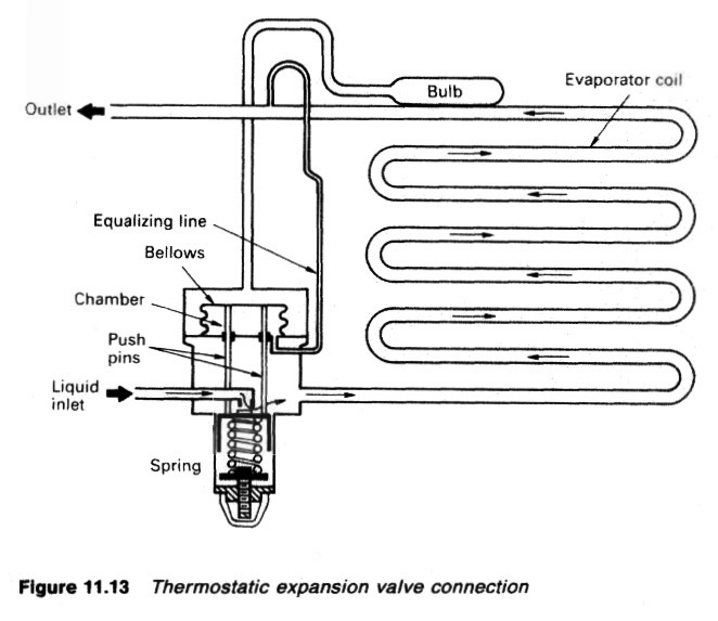
The expansion valve is the regulator through which the refrigerant passes from the high pressure side of the system to the low pressure side. The pressure drop causes the evaporating temperature of the refrigerant to fall below that of the evaporator. Thus, for example, the refrigerant can be boiled off by an evaporator temperature of — 18 deg C because the pressure drop brings the evaporating temperature of the refrigerant down to say — 24 deg C The liquid refrigerant leaves the condenser with a temperature just above that of the sea-water inlet, say 15 deg C. ....

Figure : Thermostatic expansion valve connection
Figure 11.13
Low pressure float controls
The mechanisms are similar to most other float controls, and act to maintain a constant level of liquid refrigerant in the evaporator by relating the flow of refrigerant to the rate of evaporation. It is responsive only to the liquid level which it will keep constant, irrespective of evaporator temperature or pressure. This type of valve is usually provided with a manually operated bypass valve, so that the system can be kept in operation in the event of a float valve failure or float valve servicing.
High pressure float valves
These valves are similar to low pressure valves in that they relate flow of liquid into the evaporator to the rate of vaporization. The low pressure valve controls
the evaporator liquid level directly. The high pressure valve located on the high pressure side of the system, controls the evaporator liquid level indirectly, by maintaining a constant liquid level in the high pressure float chamber.
As vapour is always condensed in the condenser at the same rate as liquid is vaporized in the evaporator, the high pressure float valve will automatically allow liquid to flow to the evaporator at the same rate as it is being evaporated, irrespective of the load on the system.
Capillary tube control
This is the simplest of all refrigerant controls and consists of a length of small diameter tubing inserted in the liquid line between the condenser and the evaporator. For a given tube bore and length the resistance will be constant, so that the liquid flow through the tube will always be proportional to the pressure difference between the condensing and evaporating pressures of the system.
Although self-compensating to some extent, this type of control will only work at maximum efficiency under one set of operating conditions, and for this reason is principally employed on close coupled package systems using hermetic or semi-hermetic compressors.
High pressure cut-out
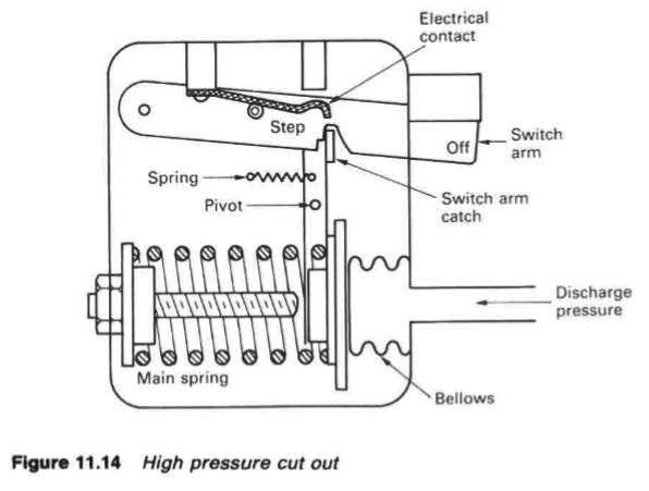
In the event of overpressure on the condenser side of the compressor (Figure 11.3) the high pressure cut-out will cause the compressor to shut down. The device is re-set by hand. There are a number of faults which cause high discharge pressure, including loss of condenser cooling, air in the system and overcharge. The bellows in the cut-out (Figure. 11.14) is connected by a small bore pipe between the compressor discharge and the condenser. The bellows tends to be expanded by the pressure and this movement is opposed by the spring.
The adjustment screw is used to set the spring pressure. During normal system operation, the switch arm is held up by the switch arm catch and holds the electrical contact in place. Excessive pressure expands the bellows and moves the switch arm catch around its pivot. The upper end slips to the right of the step and releases the switch arm so breaking the electrical contact and causing the compressor to cut-out. The machine cannot be restarted until the trouble has been remedied and the switch re-set by hand.

Figure : High pressure cut out
Driers
Where halogenated hydrocarbon refrigerants are used it is absolutely essential that driers are fitted in the refrigerant piping and most Classification Societies make this mandatory. Water can freeze on the expansion valve so causing excess pressure on the condenser side and starvation of refrigerant to the evaporator. When this occurs, the compressor will cut out due to operation of the high pressure cut-out or low pressure controller.
The presence of a small amount of water can have an effect on plant performance and driers are essential. These are usually simple cylindrical vessels, the refrigerant entering at one end and leaving at the other.
For modern installations the strainer/drier pack is replaced complete after opening the bypass and isolating the one to be replaced. Older systems are likely to have a strainer/drier partly filled with renewable drying agent. The drier, usually silica gel or activated alumina, is supported on a stiff gauze disc, overlaid with cotton wool with a similar layer above.
In most installations the driers have bypasses so that they can be isolated without interfering with the running of the plant and the drying agent renewed or re-activated (by the application of heat). If the drier is located in the liquid line it should be arranged so that the liquid enters at the bottom and leaves at the top.
This is to ensure that there is uniform contact between the liquid refrigerant and the drying agent and that any entrained oil globules will be floated out without fouling the particles of the drying agent. If located in the suction line, the gas should enter at the top and leave at the bottom so that any oil can pass straight through and out.
Summarized below various refrigeration system components, working process and maintenance guideline:
- Automatic direct expansion refrigeration- vapour compression
The basic components of any refrigeration system (Figure 11.1) working on the
vapour compression cycle, are the compressor, condenser, expansion valve,
evaporator and the refrigerant fluid which is alternately vaporized and liquefied
during the refrigeration cycle. The temperature at which a fluid boils or
condenses, is known as the saturation temperature and varies with pressure....more
-
Choice of refrigerants
Theoretically, almost any liquid can be used as a refrigerant if its pressure/temperature relationship is suitable for the conditions. Although no perfect refrigerant is known, there are certain factors which determine a refrigerant's desirability for a particular duty and the one selected should possess as many as possible of the following
characteristics.....more
-
Refrigeration systems - Chamber cooling arrangements
To avoid having an extended refrigeration circuit for cargo cooling, a brine system can be used. The brine is cooled by the evaporator and in turn cools grids or batteries. Grids provide cooling which relies on convection and conduction but air circulated through brine batteries provides a positive through cooling effect.
.....more
-
Refrigeration system components
Marine condensers are generally of the shell and tube type, designed for high pressures. There may a few coil-in-casing or other types still in use. The coolant passes through the tubes with refrigerant condensing on the outside......more
-
Refrigeration system compressors
Refrigeration compressors are usually either reciprocating, or of the rotary
screw displacement type. Centrifugal and rotary vane compressors have also
been used.....more
-
Refrigeration systems expansion valves
The expansion valve is the regulator through which the refrigerant passes from the high pressure side of the system to the low pressure side. The pressure drop causes the evaporating temperature of the refrigerant to fall below that of the evaporator. .....more
- Monitoring instruments,CO2 measurement & Heat leakage and insulation test
All necessary cargo temperature readings are obtained on modern reefers and container ships on a data logger which makes an automatic record. The temperatures and pressures relating to refrigerant gas and liquid, cooling water, brine and the ambient are also required. Most of these are obtained from direct reading instruments.
.....more
- Marine condenser assembly
The temperature of the refrigerated spaces with a direct expansion system is controlled between limits through a thermostatic switch and a solenoid valve which is either fully open to permit flow of refrigerant to the room evaporator, or closed to shut off flow. The solenoid valve is opened when the sleeve moving upwards due to the magnetic coil hits the valve spindle tee piece and taps the valve open.....more
- Comparison between refrigerants R717 ammonia & R744 carbon dioxide
The ammonia used for refrigeration systems based on the use of a compressor,
condenser, expansion valve and an evaporator (Figure 11.2) is dry (anhydrous)
in that there is no water in solution with it. It has the chemical formula NH3 but
as a refrigerant, it is coded with the number R717....more
-
Container cooling system
The air is cooled either by brine or direct expansion batteries and the containers are arranged so that one cooler can maintain a stack of containers at a given temperature. The temperature of the return air duct for each container is monitored.....more
Home page||Cooling ||Machinery||Services ||Valves ||Pumps ||Auxiliary Power ||Propeller shaft ||Steering gears ||Ship stabilizers||Refrigeration||Air conditioning ||Deck machinery||Fire protection||Ship design
||Home ||
General Cargo Ship.com provide information on cargo ships various machinery systems -handling procedures, on board safety measures and some basic knowledge of cargo ships that might be useful for people working on board and those who working in the terminal. For any remarks please
Contact us
Copyright © 2010-2016 General Cargo Ship.com All rights reserved.
Terms and conditions of use
Read our privacy policy|| Home page||


