
Home page||Steering gears ||
Detailed description of four ram gear hydraulic system
Ships from at least the 1950s, have been fitted with automatic steering, making
helmsmen redundant for deep sea passages. After the required course is set, the
automatic steering maintains direction; correcting any deviations due to the
weather.
Four ram gear hydraulic steering system
The drawing of a four ram gear (Figure 9.14) shows the Rapson slides, the
combined guide and brace arrangement previously described and the control
box with its connecting link from the rudder stock. A second link from the
stock to the rudder angle indicator transmitter, is also shown.
The hydraulic circuit (Figure 9.15) incorporates an arrangement of stop and
bypass valves in the chest VC, which enable the gear to be operated on all four
or on any two adjacent cylinders but not with two diagonally disposed
cylinders. Inactive cylinders are isolated from the pumps by valves while the
bypass valves connecting them, are opened to permit free flow of idle fluid.
Either or both duplicate independent power units may be employed with any
usable combination of cylinders.
It will be seen that the torque available from
two cylinders is only one-half of that from four, even when both power units
are working, though the speed of operation will be increased if both are used.
The mechanical arrangement of the control gear and the basic hydraulic
system, in all but their layout (Figure 9.15) are identical with the two ram gear
already described.
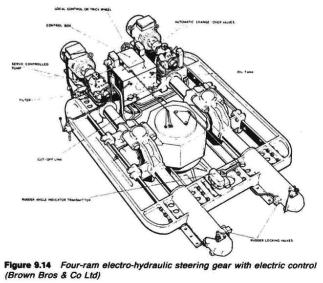
Figure 9.14 Four-ram electro-hydraulic steering gear with electric control(Brown Bros & Co Ltd)
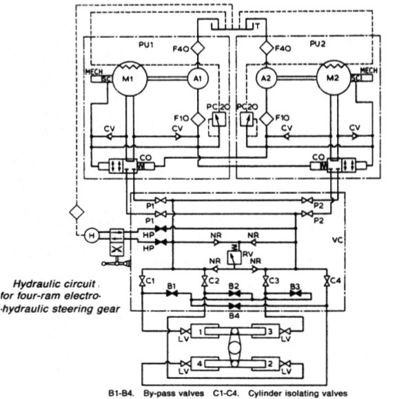
Figure 9.15 Hydraulic circuit for four-ram electro-hydraulic steering gear(Brown Bros & Co Ltd)
B1-B4. (By-pass valves) ,C1-C4. (Cylinder isolating valves)
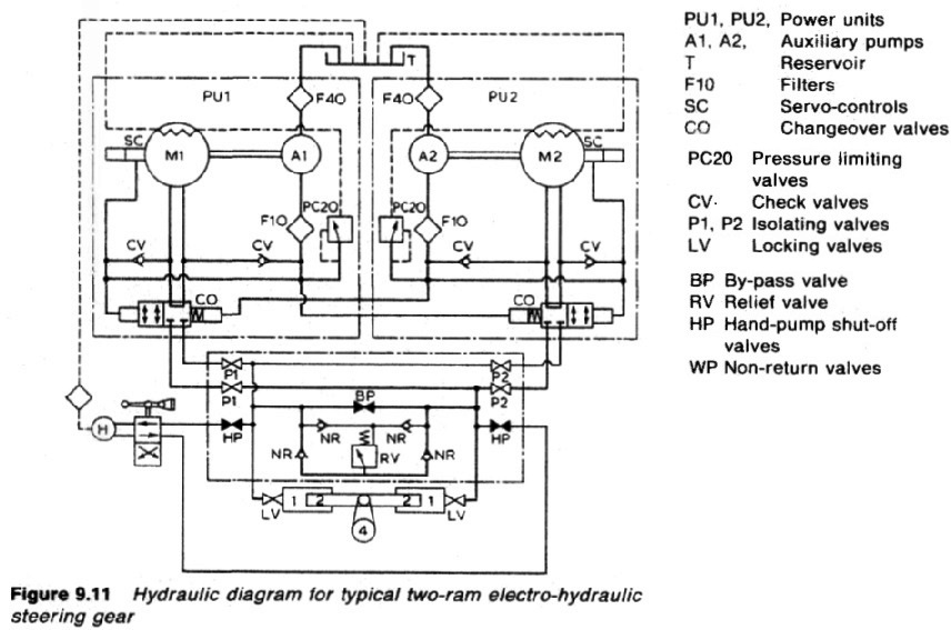
fig: 9.11 Hydraulic circuit details for four-ram electro-hydraulic steering gear(Brown Bros & Co Ltd)
The valve chest however, must cater for four cylinders in all
useful combinations. This demands four cylinder isolating valves, C1-C4, and
four bypass valves, BlB4. The emergency hand pump arrangement, its
directional control valve, the main system relief and the locking valves remain
unchanged, as do the remote, local and emergency control arrangements.
Normally, the pump and the four cylinder isolating valves, Pi, P2, C1-C4,
and the rudder locking valves LV, are open. The bypass valves BlB4 and the
emergency hand pump isolating valves HP are closed. Power units may be
brought into action or shut down, by starting or stopping the associated motors.
To change from four ram to two ram working, it is only necessary to make
two cylinders inoperative by closing their isolating valves C1-C4 and opening
the bypass valves between them.
For example to steer on cylinders 1 and 3,
valves C2 and C4 are closed; B2 and B4 are opened so that cylinders numbers 2
and 4 are isolated from the main hydraulic system and the oil in them is free to
flow from one to the other. The cylinder isolating valves and the bypass valves
are shown as separate items in diagram but each pair may be combined as a
double seating valve so that, as any cylinder is isolated from the main hydraulic
system it is automatically opened to a bypass manifold and to the other
inoperative cylinder.
Summarized below various ship steering gears general guideline:
- Ship Steering gear failures and safeguards
The hydraulic circuit incorporates an arrangement of stop and bypass valves in the chest VC, which enable the gear to be operated on all four or on any two adjacent cylinders but not with two diagonally disposed cylinders.
......
- Four-ram electro-hydraulic steering gear mechanism
The hydraulic circuit incorporates an arrangement of stop and bypass valves in the chest VC, which enable the gear to be operated on all four or on any two adjacent cylinders but not with two diagonally disposed cylinders.
......
- Enclosed hunting gear
The light construction of the combined control and hunting gears is possible
because the forces concerned are moderate. The self-contained unit is
self-lubricating, and contained in an oil-tight case.
......
- Ship steering control mechanism- use of Hydraulic telemotor
The telemotor has become, on many vessels, the stand-by steering control
mechanism, used only when the electric or automatic steering fails. It comprises
a transmitter on the bridge and a receiver connected to the steering gear
variable delivery pump, through the hunting gear.
......
- Two-ram electro-hydraulic steering gear with variable
delivery pumps
An arrangement of a two-ram steering gear with variable
delivery pumps may have a torque capacity of 120-650 kNm.
The cylinders for this gear are of cast steel but the rarns comprise a one-piece
steel forging with integral pins to transmit the movement through cod pieces
which slide in the jaws of a forked tiller end.
......
- Rudder carrier bearing & Steering gear
The rudder carrier bearing takes the weight of the rudder on a
grease lubricated thrust face. The rudder stock is located by the journal
beneath, also grease lubricated
......
- Small hand and power gears - Ship steering systems
A simpler variant of the electro-hydraulic gear, for small ships requiring rudder
torques below say, 150 kNm
......
- Four ram gear with servo-controlled axial cylinder pumps
Variants of the servo-controlled swash plate axial cylinder pump
are capable of working at 210 bar. Each pump is complete with its own torque
motor, servo-valve, cut-off mechanism, shut-off valve and oil cooler.
......
- Vane type gear - provides security of four ram steering gear
These may be regarded as equivalent to a two-ram gear, with torque capacities
depending on size. An assembly of two rotary vane gears, one above the other,
provides the security of a four ram gear.
......
- Details of two ram hydraulic steering gear arrangement
When the main pumps are at no-stroke, the auxiliary pumps dischar.
to the reservoir via a pressure-limiting valve PC20, set at 20 bar, and to t
pump casings. When the main pumps are on-stroke, the auxiliary pump
discharge to the main pump suction.
......
Home page||Cooling ||Machinery||Services ||Valves ||Pumps ||Auxiliary Power ||Propeller shaft ||Steering gears ||Ship stabilizers||Refrigeration||Air conditioning ||Deck machinery||Fire protection||Ship design
||Home ||
General Cargo Ship.com provide information on cargo ships various machinery systems -handling procedures, on board safety measures and some basic knowledge of cargo ships that might be useful for people working on board and those who working in the terminal. For any remarks please
Contact us
Copyright © 2010-2016 General Cargo Ship.com All rights reserved.
Terms and conditions of use
Read our privacy policy|| Home page||