
Home page||Steering gears ||
Two-ram electro-hydraulic steering gear with variable
delivery pumps
Figure below shows an arrangement of a two-ram steering gear with variable
delivery pumps. Such gears may have a torque capacity of 120-650 kNm.
The cylinders for this gear are of cast steel but the rarns comprise a one-piece
steel forging with integral pins to transmit the movement through cod pieces
which slide in the jaws of a forked tiller end. The rams are machined and ground
to slide in the gunmetal neck bushes and chevron type seals of the cylinders.
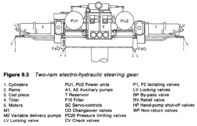
Figure 9.3 : Two-ram electro-hydraulic steering gear.
Hydraulic pressure is supplied to one cylinder or the other, by uni-directional,
variable delivery pumps, with electric drive, running at constant speed. The
pumps may be Hele-Shaw radial piston type or a development of the axial
piston V.S.G. pump. The strokes of the pump pistons in both types of pump can
be varied and the flow of oil to and from the pump can be reversed. When the
operating rod of the pump is in mid position, there is no flow of oil.
Variable delivery pumps
Variable delivery pumps can run continuously in one direction but have the
capability of an infinitely changeable discharge from zero to a maximum either
way. The principle of operation is based on altering the stroke of the pump
pistons in radial or axial cylinders, by means of a floating ring or swash plate
respectively, to change the amount of oil displaced.
There is very little shock to
the hydraulic system as the pump commences delivery, because the piston
stroke increases from zero gradually. For a small rudder movement, piston
stroke is small; the stroke becomes full only for larger rudder movements. At
the end of the rudder movement, pump discharge tapers off; it does not cease
abruptly as with constant delivery pumps which have valve control.
Non-reverse locking gear
When two pumping units are fitted and only one is running, the idle pump
might be driven in the reverse direction by fluid under pressure from the
running pump, if non-reverse locking gear (Figure 9.5) were not fitted. This
gear is integral with the flexible coupling connecting motor and pump. It
consists of a number of steel pawls so mounted on the motor coupling that,
when pumping units are running, they fly outward due to the centrifugal effect
and remain clear of the stationary steel ratchet secured to the motor supporting
structure.
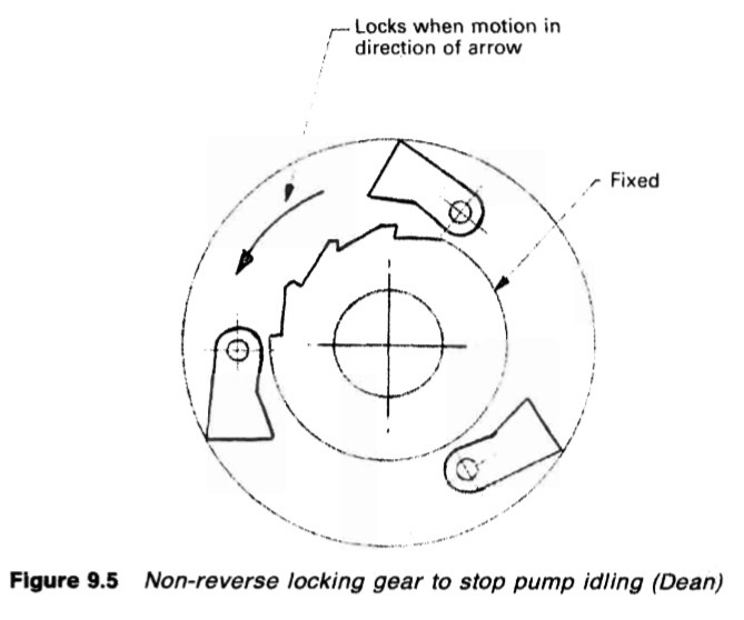
Figure 9.5 : Non-reverse locking gear to stop pump idling (Dean)
The limit of this outward movement is reached when the pawls contact the
surrounding casing, which revolves with the coupling.
When the pumps stop, the pawls return to their normal, inward position and
engage the ratchet teeth, so providing a positive lock against reverse rotation.
This action is automatic and permits instant selection and commissioning of
either unit without needing to use the pump isolating valves, which are
normally open - and are only closed in an emergency.
The swash plate axial cylinder pump
This pump (Figure 9.6) has a circular cylinder block with axial cylinders
disposed on a pitch circle around a central bore which is machined with splines
to suit the input shaft with which it revolves. The individual cylinders are
parallel with the shaft, with one end of each terminating in a drilled port at the
end face of the block. This face bears against a stationary valve plate and is
maintained in contact by spring pressure.
The spring compensates automatically
for wear. Semi-circular ports in the valve plate, in line with those from the
cylinders, are connected by external pipes to the steering cylinders. The
connection is often direct to the cylinders for two ram gears, but by way of a
change over valve chest in four ram gears.
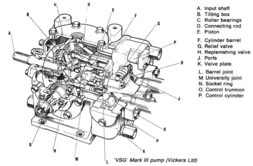
Figure 9.6 Arrangement of 'VSG-MARK-III-pump' (Vickers Ltd)
In the Mark III design, the cylinder barrel is driven by the input shaft
through a universal joint and the valve plate contact springs are supplemented
by hydraulic pressure. Each cylinder contains a piston, connected by a double
ball-ended rod to a socket ring driven by the input shaft through another
universal joint and rotating on roller thrust bearings (in some cases on Michel!
pads) within a tilt box. This is carried on trunnions and can be tilted on either
side of the vertical by an external control; the telemotor for a steering gear.
When the tilt box is vertical, the socket ring, cylinder barrel and pistons all
revolve in the same plane and the pistons have no stroke. As the box is tilted,
and with it the socket ring, stroke is given to the pistons at each half revolution,
the length of stroke being determined by the angle of tilt.
The slipper pad axial cylinder pump
This is another development of the pump described above, suitable for the
higher pressures demanded as steering gear and fin stabilizer systems were
developed. The socket ring and connecting rods are replaced by slipper pads in
the tilt box, the spherical ends of the pistons being carried in the pads.
Inclination is given to the tilt box by a servo piston, which is operated by
hydraulic pressure. Figure 9.7 shows a cut-away section.
Another variant is the 'Sunstrand' pump (Figure 9.8) in which a reversible
swashplate, vertically disposed and given the desired angular rotation by an
integral servo-piston, is used to vary the quantity and direction of the
hydraulic fluid.
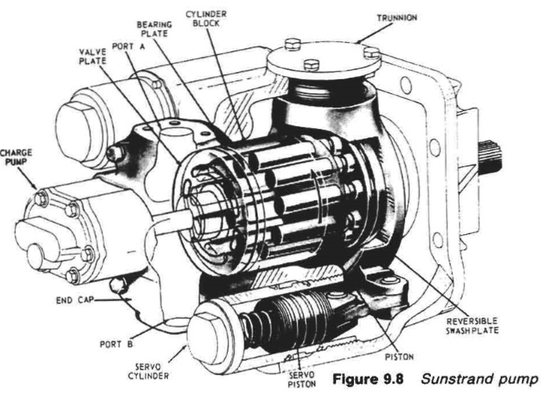
(Figure 9.8): Sunstrand-pump
Summarized below various ship steering gears general guideline:
- Ship Steering gear failures and safeguards
The hydraulic circuit incorporates an arrangement of stop and bypass valves in the chest VC, which enable the gear to be operated on all four or on any two adjacent cylinders but not with two diagonally disposed cylinders.
......
- Four-ram electro-hydraulic steering gear mechanism
The hydraulic circuit incorporates an arrangement of stop and bypass valves in the chest VC, which enable the gear to be operated on all four or on any two adjacent cylinders but not with two diagonally disposed cylinders.
......
- Enclosed hunting gear
The light construction of the combined control and hunting gears is possible
because the forces concerned are moderate. The self-contained unit is
self-lubricating, and contained in an oil-tight case.
......
- Ship steering control mechanism- use of Hydraulic telemotor
The telemotor has become, on many vessels, the stand-by steering control
mechanism, used only when the electric or automatic steering fails. It comprises
a transmitter on the bridge and a receiver connected to the steering gear
variable delivery pump, through the hunting gear.
......
- Two-ram electro-hydraulic steering gear with variable
delivery pumps
An arrangement of a two-ram steering gear with variable
delivery pumps may have a torque capacity of 120-650 kNm.
The cylinders for this gear are of cast steel but the rarns comprise a one-piece
steel forging with integral pins to transmit the movement through cod pieces
which slide in the jaws of a forked tiller end.
......
- Rudder carrier bearing & Steering gear
The rudder carrier bearing takes the weight of the rudder on a
grease lubricated thrust face. The rudder stock is located by the journal
beneath, also grease lubricated
......
- Small hand and power gears - Ship steering systems
A simpler variant of the electro-hydraulic gear, for small ships requiring rudder
torques below say, 150 kNm
......
- Four ram gear with servo-controlled axial cylinder pumps
Variants of the servo-controlled swash plate axial cylinder pump
are capable of working at 210 bar. Each pump is complete with its own torque
motor, servo-valve, cut-off mechanism, shut-off valve and oil cooler.
......
- Vane type gear - provides security of four ram steering gear
These may be regarded as equivalent to a two-ram gear, with torque capacities
depending on size. An assembly of two rotary vane gears, one above the other,
provides the security of a four ram gear.
......
- Details of two ram hydraulic steering gear arrangement
When the main pumps are at no-stroke, the auxiliary pumps dischar.
to the reservoir via a pressure-limiting valve PC20, set at 20 bar, and to t
pump casings. When the main pumps are on-stroke, the auxiliary pump
discharge to the main pump suction.
......
Home page||Cooling ||Machinery||Services ||Valves ||Pumps ||Auxiliary Power ||Propeller shaft ||Steering gears ||Ship stabilizers||Refrigeration||Air conditioning ||Deck machinery||Fire protection||Ship design
||Home ||
General Cargo Ship.com provide information on cargo ships various machinery systems -handling procedures, on board safety measures and some basic knowledge of cargo ships that might be useful for people working on board and those who working in the terminal. For any remarks please
Contact us
Copyright © 2010-2016 General Cargo Ship.com All rights reserved.
Terms and conditions of use
Read our privacy policy|| Home page||