
Home page||Steering gears ||
Ship steering control
mechanism- use of Hydraulic telemotor
The telemotor has become, on many vessels, the stand-by steering control
mechanism, used only when the electric or automatic steering fails. It comprises
a transmitter on the bridge and a receiver connected to the steering gear
variable delivery pump, through the hunting gear. Transmitter and receiver are
connected by solid drawn copper pipes. Liquid displaced in the transmitter
causes a corresponding displacement in the receiver and movement of the
pump control through the hunting gear.
The transmitter (Figure 9.9) consists of a cylinder with a pedestal base which
contains a piston operated by a rack and pinion from the steering wheel. The
make-up tank functions automatically through spring loaded relief and make-up
valves. Excess pressure in the telemotor system causes oil to be released through
the relief valve to the make-up tank and loss of oil is made up through the
lightly loaded make-up valve. The two valves are connected through a shut-off
valve, which is normally left open, and the bypass which connects both sides of
the pressure system, when the piston is in mid position. There is also a hand
operated bypass.
The tank must be kept topped up. The non-freezing working fluid is normally
a mineral oil of low viscosity and pour point, which gives some protection
against rusting. Before the general use of mineral oil, it was common to employ
a mixture of glycerol and water as the low pour point (non-freezing) working
medium.
The section through the receiver, shows two receiving cylinders in one
piston casting, with circuit pipes connected to the outer end of each ram. Any fluid
displaced in the transmitter cylinder by the piston will therefore be forced
through the pipes and circuit valve to the receiving cylinder.
The receiver rams
are fixed in the arrangement shown and any displacement of the fluid causes
the cylinder body to move along the rams against the compression of one of
the springs. The compressed spring serves to return the receiver, and with it
the transmitter, to midship position when the helmsman releases the steeringwheel.
The linkage to the pump control through the hunting lever, is fitted to
one end of the cylinder body.
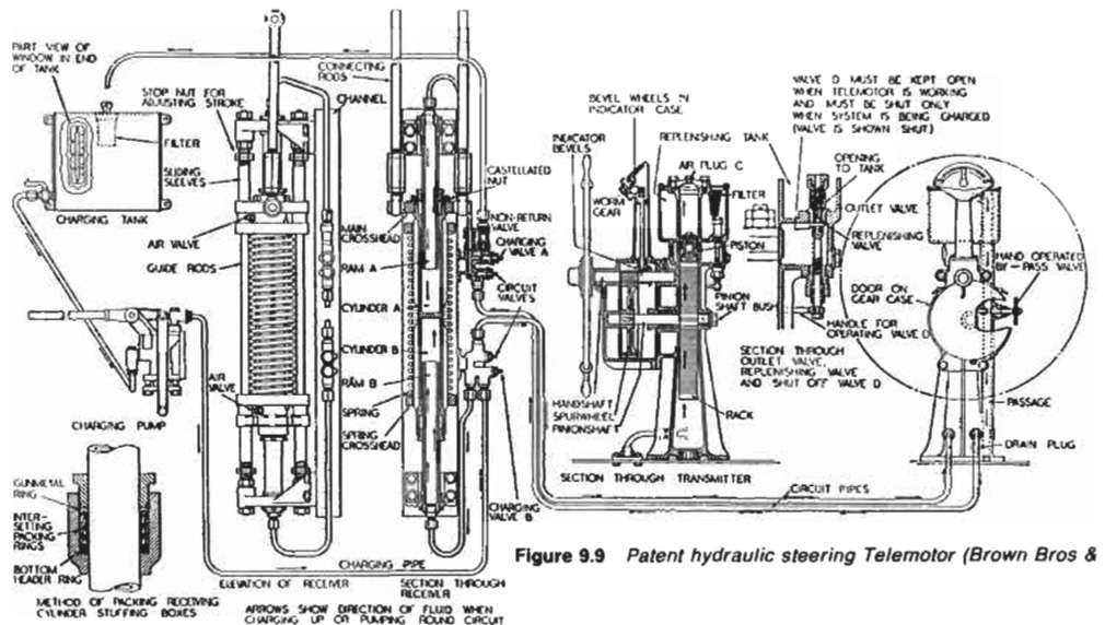
Figure :Patent hydraulic steering telemotor
Summarized below various ship steering gears general guideline:
- Ship Steering gear failures and safeguards
The hydraulic circuit incorporates an arrangement of stop and bypass valves in the chest VC, which enable the gear to be operated on all four or on any two adjacent cylinders but not with two diagonally disposed cylinders.
......
- Four-ram electro-hydraulic steering gear mechanism
The hydraulic circuit incorporates an arrangement of stop and bypass valves in the chest VC, which enable the gear to be operated on all four or on any two adjacent cylinders but not with two diagonally disposed cylinders.
......
- Enclosed hunting gear
The light construction of the combined control and hunting gears is possible
because the forces concerned are moderate. The self-contained unit is
self-lubricating, and contained in an oil-tight case.
......
- Ship steering control mechanism- use of Hydraulic telemotor
The telemotor has become, on many vessels, the stand-by steering control
mechanism, used only when the electric or automatic steering fails. It comprises
a transmitter on the bridge and a receiver connected to the steering gear
variable delivery pump, through the hunting gear.
......
- Two-ram electro-hydraulic steering gear with variable
delivery pumps
An arrangement of a two-ram steering gear with variable
delivery pumps may have a torque capacity of 120-650 kNm.
The cylinders for this gear are of cast steel but the rarns comprise a one-piece
steel forging with integral pins to transmit the movement through cod pieces
which slide in the jaws of a forked tiller end.
......
- Rudder carrier bearing & Steering gear
The rudder carrier bearing takes the weight of the rudder on a
grease lubricated thrust face. The rudder stock is located by the journal
beneath, also grease lubricated
......
- Small hand and power gears - Ship steering systems
A simpler variant of the electro-hydraulic gear, for small ships requiring rudder
torques below say, 150 kNm
......
- Four ram gear with servo-controlled axial cylinder pumps
Variants of the servo-controlled swash plate axial cylinder pump
are capable of working at 210 bar. Each pump is complete with its own torque
motor, servo-valve, cut-off mechanism, shut-off valve and oil cooler.
......
- Vane type gear - provides security of four ram steering gear
These may be regarded as equivalent to a two-ram gear, with torque capacities
depending on size. An assembly of two rotary vane gears, one above the other,
provides the security of a four ram gear.
......
- Details of two ram hydraulic steering gear arrangement
When the main pumps are at no-stroke, the auxiliary pumps dischar.
to the reservoir via a pressure-limiting valve PC20, set at 20 bar, and to t
pump casings. When the main pumps are on-stroke, the auxiliary pump
discharge to the main pump suction.
......
Home page||Cooling ||Machinery||Services ||Valves ||Pumps ||Auxiliary Power ||Propeller shaft ||Steering gears ||Ship stabilizers||Refrigeration||Air conditioning ||Deck machinery||Fire protection||Ship design
||Home ||
General Cargo Ship.com provide information on cargo ships various machinery systems -handling procedures, on board safety measures and some basic knowledge of cargo ships that might be useful for people working on board and those who working in the terminal. For any remarks please
Contact us
Copyright © 2010-2016 General Cargo Ship.com All rights reserved.
Terms and conditions of use
Read our privacy policy|| Home page||