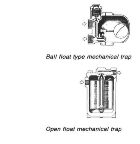
Figure 1: Ball float type mechanical trap
& Open float mechanical trap
Mechanical traps have been installed with ball floats (Figure 1) or open floats (Figure 1) for control of a needle valve to release condensate.
Thermostatic traps
Thermostatic traps (Figures 2 : a, b and c) use the expansion of an oil-filled element, a bimetallic strip or flexible bellows to actuate a valve. As the condensate temperature rises in the oil filled element type (Figure a) element A expands to close the valve D. An adjustment screw E permits the valve to be set up for condensate release at a specific temperature.
Clearly in an application where the pressure varies, there could be a broad band of operation in which the trap would be either waterlogged or passing steam. With the bimetallic strip type (Figure b) deflection of the bimetallic strip when temperature increases, closes the valve. The device will work over a
range of pressures without the need for re-adjustment and will operate satisfactorily under superheat conditions.
It is not particularly prone to damage by water hammer or vibration. In the flexible bellows type (Figure c) the bellows is filled with a mixture which boils at a lower temperature than does the steam. The trap self-compensates for operating pressure. It will be damaged if water hammer occurs and will burst if subjected to superheated steam.
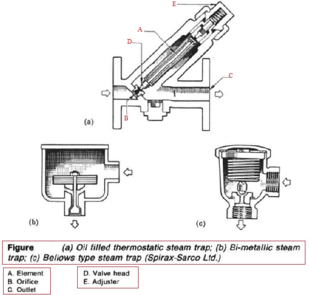
Figure 2: (a) Oil filled thermostatic steam trap; (b) Bi-metallic steam trap; (c) Bellows type steam trap (Spirax-Sarco Ltd.)
Thermodynamic steam trap
This type of trap uses the pressure energy of the steam to close the valve which consists of a simple metal disc. The sequence of operation is shown in Figure 3. In (i), disc A is raised from seat rings C by incoming pressure allowing discharge of air and condensate through outlet B. As the condensate approaches steam temperature it flashes to steam at the trap orifice. This means that the rate of fluid flow radially outwards under the disc is greatly increased. There is thus an increase in dynamic pressure and a reduction in static pressure. The disc is therefore drawn towards the seat. Due to this alone the disc will never seat.
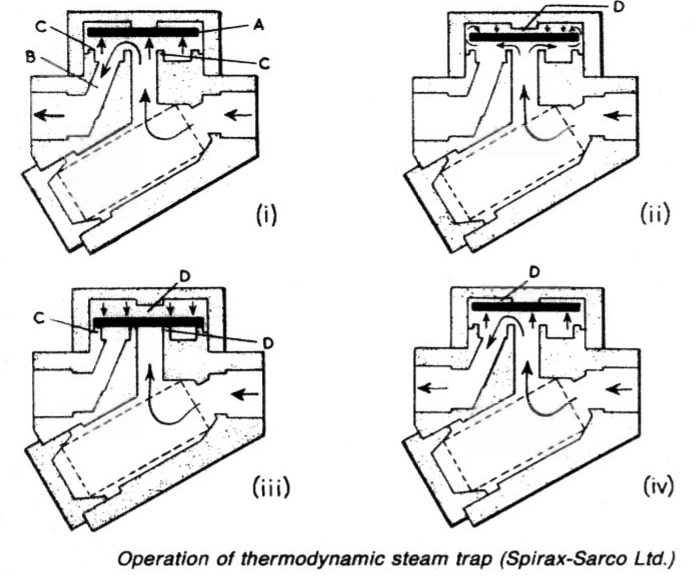
Figure 3: Operation of thermodynamic steam trap (Spirax-Sarco Ltd.)
However, steam can flow round the edge of the disc resulting in a pressure build up in the control chamber D as shown in (ii). When the steam pressure in chamber D acting over the full area of the disc (iii) exceeds the incoming condensate/steam pressure acting on the much smaller inlet area, the disc snaps shut over the orifice. This snap action is important. It removes any possibility of wire-drawing the seat, while the seating itself is tight, ensuring no leakage.
As shown in (iv) the incoming pressure will eventually exceed the control chamber pressure and the disc will be raised, starting the cycle all over again. The rate of operating will depend on the steam pressure and on the ambient air temperature. In practice, the trap will usually open after 1525 s, the length of time open depending on the amount of condensate to be discharged. If no condensate has been formed, then the trap snaps shut immediately. From the foregoing it will be seen that the trap is never closed for more than 1525 s, so condensate is removed virtually as soon as it is formed.
Vacuum or pumping traps
The layout of drain systems can often be improved by the use of automatic pumps, sometimes referred to as vacuum traps. Condensate can be drained by gravity more readily to local receivers and then pumped back to the engine room as required. Similarly engine room drains can be relieved of much back pressure by taking them to a low level hot well before pumping to a high level
boiler feed tank.
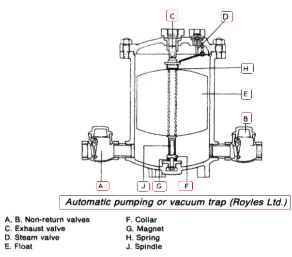
Figure 4 : Automatic pumping or vacuum trap (Royles Ltd.)
A, B. Non-return valves F. Collar C. Exhaust valve G. Magnet D. Steam valve H. Spring E. Float J. Spindle
A high level feed tank will enable the pumps to handle warm feed water and can improve the overall efficiency of the plant. A typical pumping trap is shown in Figure 4. When the trap is empty, the exhaust valve C is open and the steam valve D is closed. Water flowing into the trap through the non-return valve A raises the float E until it compresses the spring H, exerting a force which plucks the spindle J away from the magnet G so that the exhaust valve is projected into the closed position and the steam valve D is opened through the movement- of the lever. Steam is therefore admitted to the trap and drives out the water through the non-return valve B.
The float fails with the level of the water inside the trap and engages the collar F, pulling the spindle J down so that the exhaust valve opens and the steam valve closes. The cycle of operation is then repeated. Being float controlled, the trap operates only when water is flowing into it.
Maintenance of traps
A defective trap wastes steam and fails to ensure adequate heating. Poor heater performance can sometimes be traced to a defective steam trap. One remedy is to close in the steam outlet valve to perhaps half or quarter of a turn. Most traps can be regularly opened for inspection. The only exception is the thermodynamic type. When operating correctly this gives a characteristic 'click', usually at intervals of between 20 and 30 s so that its performance can be checked simply by listening.
Before inspecting any trap, it is advisable to check the strainer which should always be provided at the inlet of the trap. The contents of the strainer screen will give an indication of the cleanliness of the system. Fine dirt passing through the strainer is one of the chief causes of defective steam traps. Pieces of pipe scale or dirt jammed across the seat can prevent proper closure and if left for a period of time can give rise to wire drawing.
In most cases cleaning and reassembling should be sufficient to ensure satisfactory operation. If the thermodynamic type fails to operate after cleaning, then it could be that the disc and seat require lapping. Mechanical traps should be checked for defective floats and buckets and wear on any linkages, while the valves and seats should be renewed if necessary. In the case of thermostatic traps, the elements should be checked to ensure that they are sound. Particular care should be taken with the elements of bimetallic steam traps. Incorrect adjustment can give rise to excessive waterlogging or cause the traps to blow steam, while the elements themselves can sometimes assume a permanent 'set'.
Summarized below some of the basic procedure of machinery valves & pipeline systems :
- Valves & pipeline materials corrosion & erosion
Galvanic corrosion is a major challenge for any pipes which carry sea water. Rust is a particular corrosion problem for steel pipes exposed to contact with sea water or moisture generally and air. Pipe runs along tank tops or on deck, are examples of the latter. Steel pipes in these areas require external as well as internal protection.....
- valves-&-pipelines-strength-of-materials
The strength of materials used for pipes and fittings must be adequate for the
system pressures and possible over-pressures. Pipelines and valves, for
example, used to carry and control the flow of high temperature, high pressure
steam must obviously be made to very exacting specifications by approved
manufacturers.....
- Valves & pipelines-system cleaning & draining
It is often found, in new ships, that the bilges and bilge systems have not been
thoroughly cleaned with the result that wood, nuts, bolts, rags and other debris
are found inside valves and pipes after initial bilge pumping. These choke the
valve-chests and prevent the valves from being properly closed. They also
block strainers. ....
- Expansion arrangements
Provision must be made in pipe systems to accommodate changes in length due to change of temperature, and so prevent undue stress or distortion as pipes expand or contract.....
- Valves & cocks
Cocks and valves are designed to control or interrupt flow. This is done in cocks by rotating the plug, and in valves by lowering, raising or rotating a disc in relation to a seating surface or by controlling the movement of a ball. ...
- Butterfly valves
A butterfly valve consists basically of a disc pivoted across the bore of a ring body having the same radial dimensions as the pipe in which it is fitted.....
- Gate valves
Unlike the globe valve, gate (or sluice) valves give full bore flow without change of direction. The valve disc known appropriately as a gate,....
- Globe valves
The globe valve has a bulbous body, housing a valve seat and screw down plug or disc arranged at right angles to the axis of the pipe....
- Relief valves
Excess pressure is eased by a relief valve . This consists of a disc held closed by a spring loaded stem. The compression on the spring can be adjusted so that the valve opens at the desired pressure. ....
- Valves traps
A steam trap is a special type of valve which prevents the passage of steam but allows condensate through. It works automatically and is used in steam heating lines to drain condensate without passing any steam. ....
- Flap valves & valve chest
Scupper pipes from accommodation spaces are fitted with non-return valves. Those scuppers from spaces below the bulkhead deck, are required to be fitted with non-return valves which can be positively closed from above the bulkhead deck or, if this is not practical, with two non-return valves.....
- Quick closingvalves
Fuel oil service and some other tanks must be fitted with valves that can be closed rapidly and remotely in the event of an emergency such as fire. Wire operated valves are commonly fitted,....
- Strainers & filters
The term strainer is sometimes used specifically for a simple device made up with a single layer of coarse gauze, a very coarse wire mesh or a drilled or perforated plate. ...
Home page||
Cooling ||
Machinery||
Services ||
Valves ||
Pumps ||
Auxiliary Power ||
Propeller shaft ||
Steering gears ||
Ship stabilizers||
Refrigeration||
Air conditioning ||
Deck machinery||
Fire protection||
Ship design
||
Home ||
General Cargo Ship.com provide information on cargo ships various machinery systems -handling procedures, on board safety measures and some basic knowledge of cargo ships that might be useful for people working on board and those who working in the terminal. For any remarks please
Contact us
Copyright © 2010-2016 General Cargo Ship.com All rights reserved.
Terms and conditions of use
Read our privacy policy|| Home page||