Home page||Auxiliary Power ||
Marine auxiliary engine fuel pump - Bosch type
Bosch type fuel pump :
The most common fuel pump used on auxiliary diesel engines is the Bosch
type. This is a cam operated jerk pump with a helical groove on the plunger to
control the fuel cut-off and therefore the quantity of fuel delivered to the
cylinder for combustion.
These pumps can be arranged singly along the
camshaft, with one at each cylinder position or they may be housed in a single
block. Each pump unit contains a pump plunger and guide together with a
spring loaded delivery valve and its seat. Plungers and guides are not
interchangeable — they should be treated as combined units or elements.
Operation :
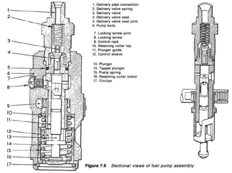
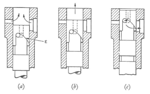
The operation of helix type pumps is shown diagrammatically in Figure 7.6.
With the plunger E at the lower limit of its travel (Figure 7.6a) fuel enters the
barrel from the surrounding suction chamber, through the two ports. As the
plunger rises, some fuel is displaced through the ports until they are just closed
(Figure 7.6b) by the top edge of the plunger. Fuel trapped above the plunger is
now forced out through the delivery valve above the top of the pump barrel.
Figure

Figure : Sectional views of fuel pump assembly

Figure 7.6:a,b,c Sectional views of fuel pump assembly
- 1. Delivery pipe connection
-
2. Delivery valve spring
- 3. Delivery valve
- 4. Delivery valve seat
- 5. Delivery valve seat joint
- 6. Pump body
- 7. Locking screw joint
- 8. Locking screw
- 9. Control rack
- 10. Retaining collar top
- 11. Plunger guide
- 12. Control sleeve
- 13. Plunger
- 14. Tappet plunger
- 15. Pump spring
- 16. Retaining collar bottom
- 17. Circlips
The pressure exerted by the rising plunger causes fuel to lift the valve and to
enter the pipe which connects the pump to the injector. As the pipe is already
full, the extra fuel which is being forced in, causes a rise in the pressure
throughout the line and lifts the needle valve of the injector. This causes fuel to
be forced into the combustion chamber in the form of a fine spray.

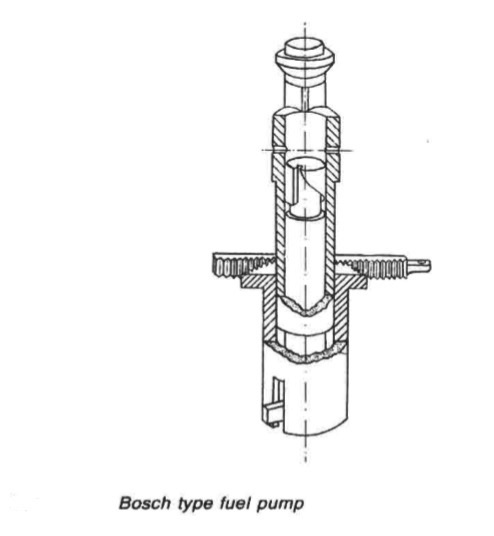
Figure 7.7 Bosch type fuel pump
As the plunger continues to move upwards, the lower edge of the control
helix uncovers the spill port, allowing fuel to be bypassed from the barrel
suction chamber through the vertical drilled hole in the plunger or via a
machined slot or channel (Figure 7.7). This allows the delivery valve to shut
under the action of its spring, and with the collapse of pressure in the pipeline,
the injector also shuts. At the junction between the delivery valve and its
guide, there is a short plane cylindrical piston which fills the seat aperture as the
valve closes. This emphasizes pressure drop in the delivery pipe so that the
injector closes sharply.
The actual plunger stroke is constant, but an effective stroke depends on
which part of the helix is moving up and down in line with the spill port. The
effective stroke can be set between maximum fuel and no fuel. The latter
setting, means that fuel spills for the full length of the plunger stroke. The
plunger is moved around to the required position by the rack and quadrant
(Figure 7.7).
The quadrant collar is on a sleeve which has two vertical slots at
the bottom. Two lugs projecting from the lower part of the plunger move up
and down in these slots as the plunger reciprocates. Rotary movement of the
sleeve (which has no vertical motion) moves the plunger. The rack which
meshes with the toothed quadrant is externally connected to suitable linkage
from the governor and the manual control lever.
Summarized below some of the basic procedure of marine auxiliary machinery :
- Auxiliary engine general construction
Major problems have been experienced on large slow-speed
engines with some of the poor quality bunkers such as those containing
catalytic fines. Fuel should conform to the specification given in the instruction
book for the engine.
......
- Auxiliary engine back pressure turbine
Many ships have used an auxiliary steam turbine as a primary pressure reducing stage before passing the steam to other auxiliaries demanding steam at a substantially lower pressure than that available. Such an arrangement gives a heat balance which is far more favourable than that obtained with a pressure reducing valve......
- Auxiliary engine fuel pump
The most common fuel pump used on auxiliary diesel engines is the Bosch
type. This is a cam operated jerk pump with a helical groove on the plunger to
control the fuel cut-off and therefore the quantity of fuel delivered to the
cylinder for combustion.
......
- Auxiliary engine common fuel injector
Fuel is delivered to an annular space in the nozzle via a hole, drilled through
the nozzle body from the inlet. The nozzle valve is forced from its seat in the
nozzle body by the pressure of fuel from the pump, acting on the shoulder of
the needle valve.
......
- Auxiliary engine cooling system
A variety of cooling systems may be adopted for marine auxiliary engines but
the most commonly used is the simple closed circuit system . Sea
water is passed through the intercooler, the oil cooler and then the jacket water
cooler in series flow.
......
- Auxiliary engine hydraulic governor
When used for alternating current power generation, a diesel engine is normally fitted with a hydraulic governor. This incorporates a centrifugal speed sensing device (spring loaded flyweights) controlling a suitably damped oil operated servo-cylinder through a pilot valve.
......
- Auxiliary engine speed governing system
Unlike propulsion turbines, generator turbines work at constant speed and must be governed accordingly. Classification Society rules require that there must be only a 10% momentary and a 6% permanent variation in speed when full load is suddenly taken off or put on.
......
- Auxiliary engine tracing faults
The failure of an engine to start or problems while running may be traced to
faults with the fuel injection system or other possible causes. Instruction
manual guidance on fault finding and remedies will include some of the typical
problems
......
- Generators driven from the main propulsion
Generators can variously be driven from the propeller shaft, through a gearbox or by being mounted on the engine itself.
......
- Exhaust gas boilers
The original exhaust gas boilers or economizers were of simple construction and produced, from the low powered engines of the time, a very moderate amount of steam. As large slow speed engine powers increased, the larger quantity of steam that could be generated from otherwise wasted exhaust energy,
......
- Auxiliary engine Turbo generator construction
Turbo-generator construction-For electrical power generation, turbines are conventionally horizontal axial flow machines of the impulse reaction type. They may exhaust either to an integral condenser (invariably underslung) or to a separate central auxiliary condenser or the ship's main condenser.
......
- Caterpillar engine fuel system
The range of larger Caterpillar engines use helix-type fuel pumps driven from a
separate camshaft.......
Home page||Cooling ||Machinery||Services ||Valves ||Pumps ||Auxiliary Power ||Propeller shaft ||Steering gears ||Ship stabilizers||Refrigeration||Air conditioning ||Deck machinery||Fire protection||Ship design
||Home ||
General Cargo Ship.com provide information on cargo ships various machinery systems -handling procedures, on board safety measures and some basic knowledge of cargo ships that might be useful for people working on board and those who working in the terminal. For any remarks please
Contact us
Copyright © 2010-2016 General Cargo Ship.com All rights reserved.
Terms and conditions of use
Read our privacy policy|| Home page||


