Home page||Auxiliary Power ||
Marine auxiliary engine speed governing system
Why Governing ?
Unlike propulsion turbines, generator turbines work at constant speed and must be governed accordingly. Classification Society rules require that there must be only a 10% momentary and a 6% permanent variation in speed when full load is suddenly taken off or put on. On an alternating current installation it is required that the permanent speed variations of machines intended for parallel operation must be equal within a tolerance of ±0.5%. In addition to the constant speed governor an overspeed governor or emergency trip is also fitted.
Speed-governing system
Speed governing systems consist of three main elements:
1. A speed sensing device, usually a centrifugal flyweight type governor driven through worm and bevel gearing from the turbine shaft.
2, A linkage system from the governor to the steam and throttle valve; on larger turbines this is an oil operated relay consisting of a pressure balanced pilot valve controlling a supply of high pressure oil to a power piston.
3, A double-beat balanced steam throttle valve which regulates the amount of steam passing to the turbine nozzles, according to the speed and electrical load.
To ensure stability, that is freedom from wandering or hunting of the speed, the system is designed to give a small decrease in speed with increase in load. The usual amount of this decrease, called the 'speed droop' of the governor, is 3% between no load and full load. If the full load is suddenly removed, there will be a momentary speed increase to a value of 7—10% above normal before it returns to a value of 3% above normal above the full load speed (the droop value).
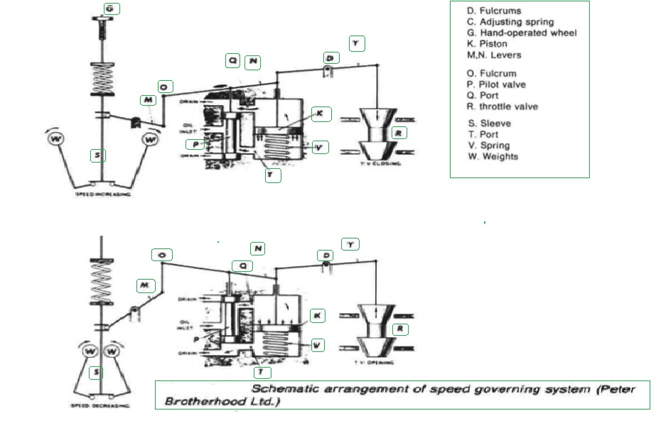
Similarly if the full load is suddenly applied, a momentary fall in speed of 4-7% below normal will occur before recovery. Figure 1 is a simplified schematic arrangement of a typical speed governing system from which the sequence of events during load changes may be more easily followed. In the diagram the throttle valve is operated via lever Y.

Figure 1 Schematic arrangement of speed governing system (Peter Brotherhood Ltd.)
Overspeed trip
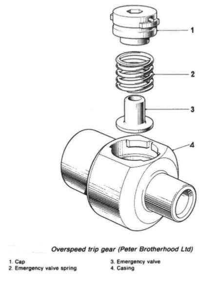
Overspeed occurs when the load is suddenly thrown off and while this is normally rectified by the speed governor, an emergency trip is always fitted. A common type is illustrated in Figure 2.

Figure 2: Overspeed trip gear (Peter Brotherhood Ltd)
D. Fulcrums O. Fulcrum S. Sleeve C. Adjusting spring P. Pilot valve T. Port G. Hand-operated wheel Q. Port V. Spring K. Piston R. throttle valve W, Weights M,N. Levers
1. Cap 3. Emergency valve 2. Emergency valve spring 4. Casing
An unbalanced steel valve 3, located in the pinion shaft extension, is held on to the valve seat by a helical spring 2, while the speed of pinion shaft remains below tripping speed. If the speed increases 10—15% above the turbine rated speed, the centrifugal effect on the trip valve, overcomes the spring force and the valve lifts rapidly from the valve seat. This allows lubricating oil, fed to the centre of the shaft extension through an orifice plate, to escape.
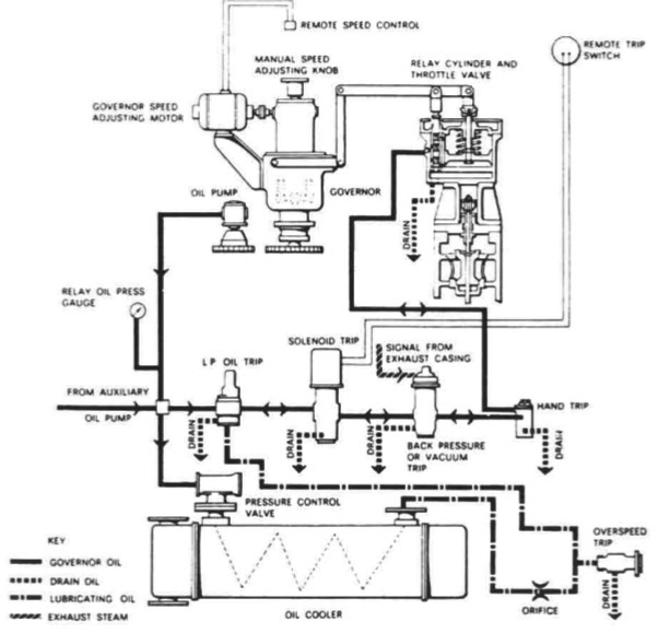
Oil system pressure drops to zero downstream from the orifice and this causes the low pressure oil trip to operate and drain oil from the relay cylinder. The relay cylinder spring raising the relay piston and closing the throttle valve cuts off the steam supply to the inlet of the turbine. It is vital to maintain the trip gear in good working order and this can be greatly aided by testing at regular intervals. In addition to an overspeed trip it is customary to fit a low pressure oil trip to steam turbines and frequently a back pressure trip (Figure 3) is fitted.

Figure 3:Governor control oil system (Peter Brotherhood Ltd)
Summarized below some of the basic procedure of marine auxiliary machinery :
- Auxiliary engine general construction
Major problems have been experienced on large slow-speed
engines with some of the poor quality bunkers such as those containing
catalytic fines. Fuel should conform to the specification given in the instruction
book for the engine.
......
- Auxiliary engine back pressure turbine
Many ships have used an auxiliary steam turbine as a primary pressure reducing stage before passing the steam to other auxiliaries demanding steam at a substantially lower pressure than that available. Such an arrangement gives a heat balance which is far more favourable than that obtained with a pressure reducing valve......
- Auxiliary engine fuel pump
The most common fuel pump used on auxiliary diesel engines is the Bosch
type. This is a cam operated jerk pump with a helical groove on the plunger to
control the fuel cut-off and therefore the quantity of fuel delivered to the
cylinder for combustion.
......
- Auxiliary engine common fuel injector
Fuel is delivered to an annular space in the nozzle via a hole, drilled through
the nozzle body from the inlet. The nozzle valve is forced from its seat in the
nozzle body by the pressure of fuel from the pump, acting on the shoulder of
the needle valve.
......
- Auxiliary engine cooling system
A variety of cooling systems may be adopted for marine auxiliary engines but
the most commonly used is the simple closed circuit system . Sea
water is passed through the intercooler, the oil cooler and then the jacket water
cooler in series flow.
......
- Auxiliary engine hydraulic governor
When used for alternating current power generation, a diesel engine is normally fitted with a hydraulic governor. This incorporates a centrifugal speed sensing device (spring loaded flyweights) controlling a suitably damped oil operated servo-cylinder through a pilot valve.
......
- Auxiliary engine speed governing system
Unlike propulsion turbines, generator turbines work at constant speed and must be governed accordingly. Classification Society rules require that there must be only a 10% momentary and a 6% permanent variation in speed when full load is suddenly taken off or put on.
......
- Auxiliary engine tracing faults
The failure of an engine to start or problems while running may be traced to
faults with the fuel injection system or other possible causes. Instruction
manual guidance on fault finding and remedies will include some of the typical
problems
......
- Generators driven from the main propulsion
Generators can variously be driven from the propeller shaft, through a gearbox or by being mounted on the engine itself.
......
- Exhaust gas boilers
The original exhaust gas boilers or economizers were of simple construction and produced, from the low powered engines of the time, a very moderate amount of steam. As large slow speed engine powers increased, the larger quantity of steam that could be generated from otherwise wasted exhaust energy,
......
- Auxiliary engine Turbo generator construction
Turbo-generator construction-For electrical power generation, turbines are conventionally horizontal axial flow machines of the impulse reaction type. They may exhaust either to an integral condenser (invariably underslung) or to a separate central auxiliary condenser or the ship's main condenser.
......
- Caterpillar engine fuel system
The range of larger Caterpillar engines use helix-type fuel pumps driven from a
separate camshaft.......
Home page||Cooling ||Machinery||Services ||Valves ||Pumps ||Auxiliary Power ||Propeller shaft ||Steering gears ||Ship stabilizers||Refrigeration||Air conditioning ||Deck machinery||Fire protection||Ship design
||Home ||
General Cargo Ship.com provide information on cargo ships various machinery systems -handling procedures, on board safety measures and some basic knowledge of cargo ships that might be useful for people working on board and those who working in the terminal. For any remarks please
Contact us
Copyright © 2010-2016 General Cargo Ship.com All rights reserved.
Terms and conditions of use
Read our privacy policy|| Home page||


