
Home page||Propeller shaft ||
Fixed pitch propellers- Methods of mounting
The normal method of manufacture for a fixed pitch propeller, is to cast the blades integral with the boss and after inspection and marking, to machine the
tapered bore and faces of the boss before the blades are profiled by hand with reference to datum grooves cut in the surfaces or with an electronically controlled profiling machine. Finally the blades are ground and polished to a smooth finish. Built-up propellers, with blades cast separately and secured to the propeller boss by studs and nuts, were made obsolete as improvements permitted the production of larger one piece castings.
The advantages of built-up propellers were the ease of replacing damaged blades and the ability to adjust the pitch, but these were outweighed by the loss of efficiency resulting from restricted width at the blade root, the greater thickness required to maintain strength and the larger hub diameter.
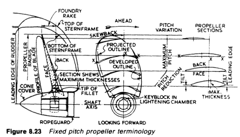
Figure : Fixed pitch propeller terminology
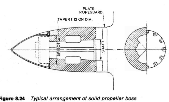
Figure : Figure 8.24 Typical arrangement of solid propeller boss
Methods of mounting propellers
Traditionally, fixed pitch propellers have been fitted to the tailshaft with a key and taper (Figure 8.24) being forced on to the taper by the tightening of a nut (see the section on sea-water lubricated stern tubes and inspection). The key was intended as a safeguard either against poor fitting, or against reduced grip due to higher sea-water temperature and differential expansion of bronze hub and steel shaft.
Keyless fitting where reliance is placed entirely on a good interference fit, has proved effective, however, and this method removes problems associated with keyways and facilitates propeller mounting and removal.Many fixed propellers are of course flange mounted, being held by bolts as shown in the section on split stern bearings. For these, outward removal of the tailshaft is made possible with the use of a muff coupling.
Keyed propellers
For the conventional key and taper arrangement, keyways are milled in the shaft taper and the key accommodated in the bore of the hub, by slots
machined through. Ideally, the hub and shaft tapers would be accurately matched and the hub would be stretched by being forced past the point of fit on the shaft taper, by the propeller nut. The 'push up' of a few millimetres is calculated to give a good interference fit. Torque in the ideal condition is transmitted totally by the interference fit, with the key being merely a back up. If conditions are not as intended, fatigue cracks can occur at the forward end of the keyway and more serious fatigue cracks may result from fretting damage (or corrosion) particularly in high-powered single screw ships.
Keyless propellers
The success of a keyless propeller depends on the accuracy of the hub and shaft tapers and correct grip from the stretched propeller hub on the shaft. The degree of stretch (or strain) is controlled by push up. It must ensure adequate grip despite any temperature changes and consequent differential expansion of bronze hub and steel shaft. It must also avoid over stressing of the hub and in particular any permanent deformation.
Lloyds require that the degree of interference be such that the frictional force at the interface can transmit 2.7 times the nominal torque when the ambient temperature is 35°C Lloyds also require that at 0°C the stress at the propeller bore, as given by the Von Mises stress criterion, shall not exceed 60% of the 0.2% proof stress of the propeller material as measured on a test bar.
Pilgrim nut method
The Pilgrim nut system used with the shaft and bore surfaces dry and degreased (except for cast steel propellers where wiping of the bore with an oil soaked rag is recommended) achieves the correct push up by a calculation based on the predictable friction of dry surfaces. The calculation gives the
hydraulic pressure suitable for the prevailing ambient temperature to produce the required push up. The operation is of course checked by measuring the push up and the hub movement relative to the increase of jacking pressure is monitored by a dial gauge.
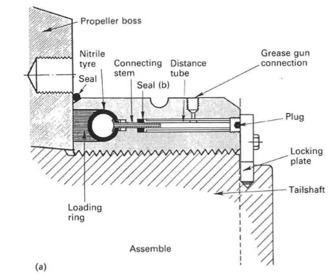
Figure :
The Pilgrim nut (Figure 8.25a) employed for propeller mounting
The Pilgrim nut (Figure 8.25a) employed for propeller mounting, has an internal nitrile rubber tube which when inflated hydraulically, forces a steel loading ring against the hub. Outward movement of the ring from the iush position must not exceed one third of the ring width, to avoid rupture of the rubber tube.
Temperature of hub and shaft are recorded and also used to find the correct final push up pressure from the table provided in the instruction book. The propeller, after a check with the blue marker of the mating surfaces, is positioned and initially jacked on to the shaft taper, before the Pilgrim nut is used to apply an initial loading of perhaps 67 bar pressure.
A reference mark is made at this point about 25 mm from the forward end of the hub. The nut is then turned until the loading ring is again flush (venting hydraulic fluid) before full pressure is applied. During this stage, the dial gauge should show the movement. A second mark 25 mm from the forward face of the hub is then made. Push up, registered by the distance between the two reference marks, is measured and noted. The nut is again vented and turned to bring the loading ring to the flush position and finally nipped up with a tommy bar.
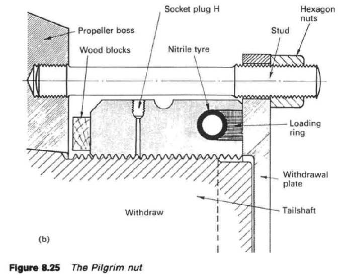
Figure : pilgrim nut with a withdrawal plate and studs
The Pilgrim nut can be reversed and used with a withdrawal plate and studs (Figure 8.25b) for removal of the propeller. To safeguard against any violent movement at release, wooden blocks are inserted as shown, and a gap of only a little more than the push up distance is left. The Pilgrim keyless system owes its name to T. W. Bunyan.
The SKF system
The oil injection system of propeller mounting is associated with the name of SKF. With this method, instead of a dry push up, oil is injected (Figure 8.26) between the shaft taper and the bore of the propeller by means of high pressure pumps. Oil penetration is assisted by a system of small axial and circumferential grooves or a continuous helical groove, machined in the propeller bore. The oil reduces the coefficient of friction between the surfaces to about 0.015.
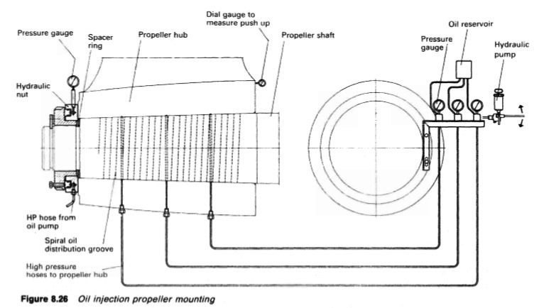
Figure : oil injection propeller mounting
A hydraulic ring jack is arranged between the shaft nut and the aft face of the propeller boss, and with this it is a simple matter to push the propeller up the shaft taper by the required amount, overcoming the friction force and the axial component of the radial pressure. When the oil injection pressure is released, the oil is forced back from between the shaft/bore surfaces leaving an interference fit with a coefficient of friction of at least 0.12. When it is required to remove the propeller, the process is equally simple and even quicker with the injection of oil between the surfaces obviating the need for any form of heating or mechanical withdrawal equipment.
Figure 8.27 Hub with cast iron sleeve
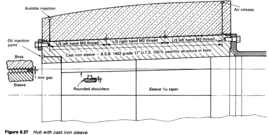
Figure : Hub with cast iron sleeve
Precautions are necessary to prevent the propeller jumping at release. A development of the keyless method involves a cast iron sleeve
(Figure 8,27) which is bonded into the propeller boss with a special form of Araldite which is injected under pressure. The sleeve is machined and bedded to the shaft taper but can be used to adapt a general purpose spare propeller to a particular shaft taper. The sleeve is easier to handle when machining and bedding than a complete propeller. Another benefit is that cast iron has a coefficient of friction nearer to that of the shaft than to the propeller bronze,
Summarized below some of the basic procedure of marine propeller shaft :
- Propeller shaft materials and couplings
The intermediate shafting and the propeller shaft for a fixed propeller are of
solid forged ingot steel and usually with solid forged couplings. Shafts are
machined all over but of a larger diameter and smooth turned in way of the
bearings.
......
- Fixed pitch propeller
The normal method of manufacture for a fixed pitch propeller, is to cast the blades integral with the boss and after inspection and marking, to machine the
tapered bore and faces of the boss before the blades are profiled by hand with reference to datum grooves cut in the surfaces or with an electronically controlled profiling machine.
......
- Controllable pitch propeller
Controllable pitch propellers are normally fitted to a flanged tailshaft as the operating mechanism is housed in the propeller boss. As its name implies, it is possible to alter the pitch of this type of propeller to change ship speed or to adjust to the prevailing resistance conditions.
......
- Propeller thrust block
The main thrust block transfers forward or astern propeller
thrust to the hull and limits axial movement of the shaft. Some axial clearance is essential to
allow formation of an oil film in the wedge shape between the collar and the
thrust pads
......
- Propeller shaft gears and clutches
For medium-speed engine installations in large ships (as opposed to coasters or intermediate sized vessels) reduction gears are needed to permit engines and propellers to run at their best respective speeds. Their use also permits more than one engine to be coupled to the same propeller. Gearboxes are available from manufacturers in standard sizes.
......
- Propeller shaft check
The intention of good alignment is to ensure that bearings are correctly loaded
and that the shaft is not severely stressed. Alignment can be checked with
conventional methods, employing light and targets, laser or measurements
from a taut wire.
......
- Propeller shaft bearings check
The intermediate shafting between the tailshaft and main engine,
gearbox or thrustblock may be supported in plain, tilting pad or roller bearings.
......
- Oil lubricated stern tube
Progress from sea-water to early oil-lubricated stern tubes involved an
exchange of the wooden bearing in its bronze sleeve for a white metal
lined cast iron (or sometimes bronze) bush. Oil retention and exclusion of
sea water necessitated the fitting of an external face type seal.
......
- Water lubricated stern tube
The traditional stern bearing is water-lubricated and consists of a
number of lignum vitae staves held by bronze retaining strips, in a gunmetal
bush. Lignum vitae is a hardwood with good wear characteristics and is
compatible with water.
......
- Stern tube sealing arrangement
There are basically three sealing arrangements used for stern bearings. These are:
Simple stuffing boxes filled with proprietary packing material. Lip seals, in which a number of flexible membranes in contact with the
shaft, prevent the passage of fluid along the shaft.
& Radial face seals, in which a wear-resistant face fitted radially around the
shaft,
......
- Stern tube bearings
To avoid the necessity for drydocking when an examination of stern bearings
amid tailshaft is needed, split stern bearings were developed. A suitable
outboard sealing arrangement and design, permits the two halves of the
bearing to be drawn into the ship, exposing the shaft and the white metal
bearing.
......
Home page||Cooling ||Machinery||Services ||Valves ||Pumps ||Auxiliary Power ||Propeller shaft ||Steering gears ||Ship stabilizers||Refrigeration||Air conditioning ||Deck machinery||Fire protection||Ship design
||Home ||
General Cargo Ship.com provide information on cargo ships various machinery systems -handling procedures, on board safety measures and some basic knowledge of cargo ships that might be useful for people working on board and those who working in the terminal. For any remarks please
Contact us
Copyright © 2010-2016 General Cargo Ship.com All rights reserved.
Terms and conditions of use
Read our privacy policy|| Home page||