
Home page||Propeller shaft ||
Marine propeller shaft- Gears and clutches arrangement
Propeller shaft, tail shaft The aftermost section of the propulsion shafting in the stern
tube in single screw ships and in the struts of multiple screw ships to which the propeller
is fitted.
Propulsion shafting constitutes a system of revolving rods that transmit power and motion from
the main drive to the propeller. The shafting is supported by an appropriate number of
bearings.
Gears and clutches:
For medium-speed engine installations in large ships (as opposed to coasters or intermediate sized vessels) reduction gears are needed to permit engines and propellers to run at their best respective speeds. Their use also permits more than one engine to be coupled to the same propeller. Gearboxes are available from manufacturers in standard sizes. Firms produce a standard range for different powers of single and multiple input, single reduction gearboxes for medium- (or high-speed engines) in a number of frame sizes.
The input and output shafts for single input gears, may be either horizontally offset, vertically offset or coaxially positioned. From the appropriate selection chart, using figures for engine power, engine speed and reduction ratio (also Classification Society correction for ice if applicable), the size and weight of the appropriate gearbox can be found.
Ship manoeuvring is of course improved with twin screws and this is an added safeguard against total loss of power due to engine breakdown. The disposition of two engines and shafts can sometimes be improved with the use of offset gearboxes. Normally twin screw propellers turn outward when running ahead, i.e. when viewed from astern the port propeller turns anticlockwise and the starboard propeller turns clockwise. (Inward turning propellers, tend to make the movement of the stern unpredictable when manoeuvring and have given rise to other problems.)
Figure 8.28 (a) Single piston servomotor (KaMeWa) (opposite); (b) Detail of KaMeWa S1 propeller hub
Key to Figure 8.28a
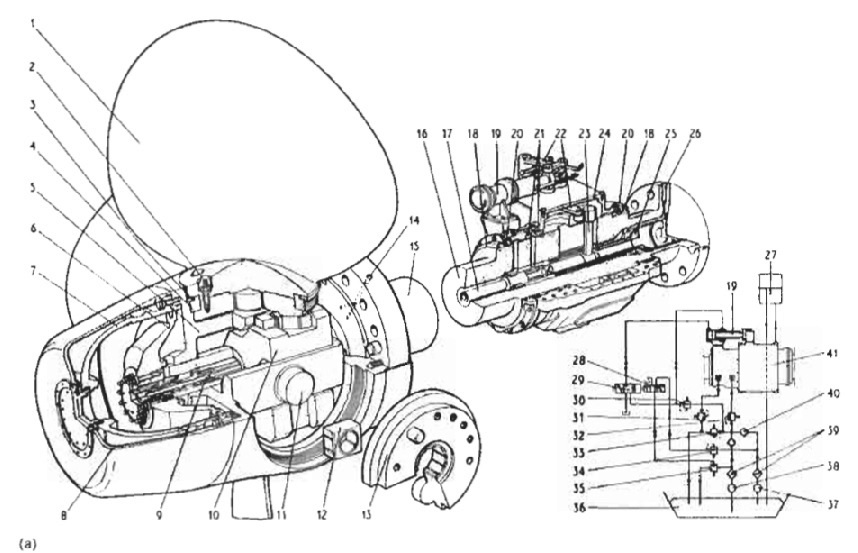
Figure : single-piston-servometer
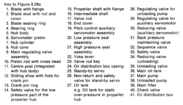
Figure : single-piston-servometer-details
Reverse reduction gearbox
Reversing with the use of a gearbox, after reducing engine speed as necessary, means that continually starting on cold air is avoided and less compressed air capacity is required. Reverse/reduction gearboxes, like straight reduction gears, are also obtainable in standard sizes, with manufacturers' charts for selection. Gear lubrication is by a self-contained system on many sets. There are various arrangements possible for the shafts in a reverse/reduction gearbox to suit the required location of the engine input or drive shaft and the driven or output shaft. The sketch (Figure 8.29) shows a simplified, flat arrangement for ease of explanation.

Figure : Reverse/reduction gearbox arrangement
The drive from the engine input shaft to the counter shaft, is through teeth on the outsides of both clutch housings, which are in continuous mesh. When the control lever is set for ahead running, the control valve supplies oil pressure to the ring piston of the ahead clutch. When the control lever is set for astern running, the control valve supplies oil pressure to the ring piston of the astern clutch. When either clutch is engaged, its pinion provides a drive to the large gear wheel of the driven shaft and the other pinion rotates freely.
Oil pressure required for clutch operation is built up by a gear pump driven from the input shaft. Lubrication is by means of overflow oil. The propeller thrust on the driven shaft is taken up by the thrust bearing. The driven (propeller) shaft, for ahead running, rotates in the opposite direction to the drive or input shaft. For astern running, the driven (propeller) shaft rotates in the same direction as the drive shaft. To stop the propeller shaft, the control is moved to the neutral position and both clutches are disengaged.
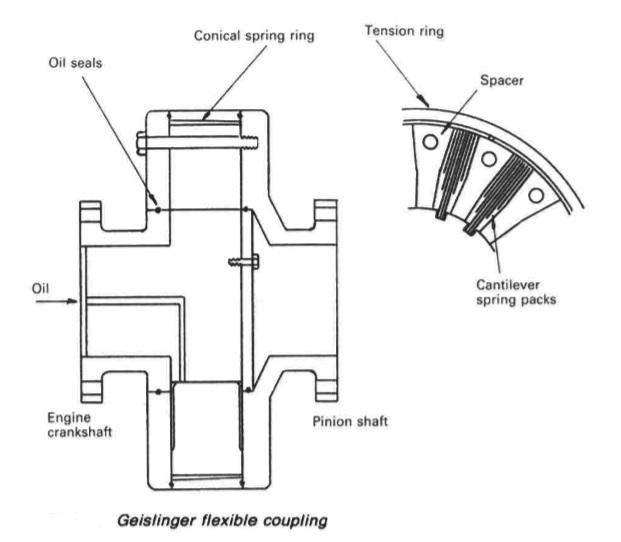
Figure : Geislinger flexible coupling
Flexible couplings
Where a gearbox is fitted, a torsionally flexible coupling (Figure 8.30) is necessary between the medium-speed diesel and the reduction gear. The coupling is necessary because the periodic application and reduction of torque as engine cylinders fire in turn, tends to result in alternate loading and unloading of the gear teeth. The torsional vibration effect is sufficient to cause serious gear tooth damage.
Flexible couplings may be installed as separate entities or in conjunction with air or oil operated clutches. Flexible couplings may be built in a common casing with the clutch. Apart from protecting the gears, flexible couplings, are also able to withstand slight misalignment. The Gieslinger coupling shown in Figure 8.30 has a housing and hub
connected by leaf springs, which flex in service to absorb torsional effects from the engine.
Figure 8.30
Air operated clutches
Clutches which are not part of the gearbox, are usually air activated, with pads or linings which make either radial or axial contact. The application force for the friction pads or linings, is supplied by compressed air in a reinforced neoprene rubber tube. The compressed air is filtered and moisture is removed by drains provided in the system. Air pressure is monitored and the low pressure alarm is particularly important. Some form of rotary connection between the air supply pipe and the clutch is necessary, with the valve controlling the air supply to the clutch tube being operated by hand or remotely controlled by a solenoid or air pressure.
For a radial air operated clutch (Figure 8.31) the compressed air expands an actuating tube around the outside of the friction pads. Inward expansion of the tube forces the pads into contact with the friction drum. The transmission of torque relies on the air pressure and loss of pressure would allow slip. The open construction of the clutch allows air access for pad cooling and the expanding tube compensates for wear. Springs (not shown) are incorporated
for disengagement of the clutch, which is also assisted by centrifugal effect. This type of clutch has been supplied in combination with a Geislinger coupling.
Figure 8.31
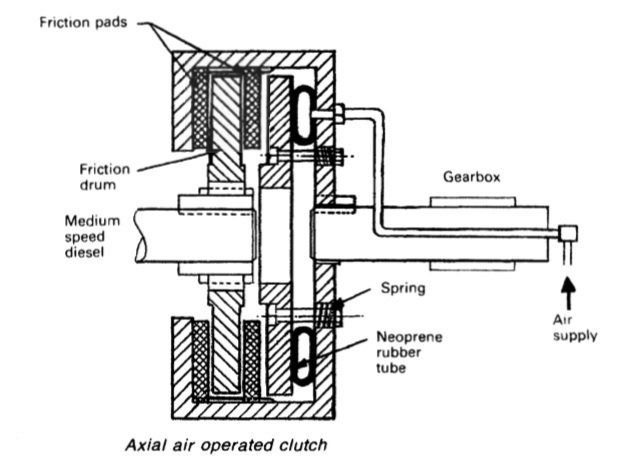
Figure : Axial air operated clutch
Axial air operated clutch
This type of clutch also uses a neoprene tube which is inflated by compressed air. Expansion of the tube (Figure above) produces a sandwich action between
friction pads and disc. The friction disc or drum is spline mounted and therefore has axial float. The friction pads are also free to float axially; being mated with teeth machined peripherally inside the casing. Springs cause disengagement of the clutch when the tube is deflated. Clutches produced by Wichita have a larger number of friction dies and pads than shown in Figure 8.32, which is intended to show the operating principle of axial air clutches.
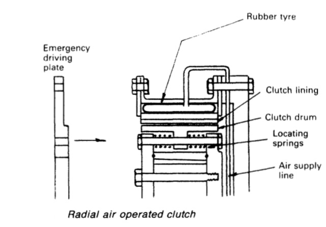
Figure : Radial air operated clutch
Emergency operation
Failure of the air supply or other fault could render a clutch inoperative. To make provision for this eventuality, an emergency driving plate (Figure 8.31) or set of temporary coupling bolts is provided. The emergency arrangement shown, is for a combined clutch and coupling. Prolonged use of the emergency solid coupling arrangement can result in serious damage to gear teeth. (The gear box of at least one medium-speed engined ship had to be expensively replaced after six months operation with the emergency coupling arrangement.)
Summarized below some of the basic procedure of marine propeller shaft :
- Propeller shaft materials and couplings
The intermediate shafting and the propeller shaft for a fixed propeller are of
solid forged ingot steel and usually with solid forged couplings. Shafts are
machined all over but of a larger diameter and smooth turned in way of the
bearings.
......
- Fixed pitch propeller
The normal method of manufacture for a fixed pitch propeller, is to cast the blades integral with the boss and after inspection and marking, to machine the
tapered bore and faces of the boss before the blades are profiled by hand with reference to datum grooves cut in the surfaces or with an electronically controlled profiling machine.
......
- Controllable pitch propeller
Controllable pitch propellers are normally fitted to a flanged tailshaft as the operating mechanism is housed in the propeller boss. As its name implies, it is possible to alter the pitch of this type of propeller to change ship speed or to adjust to the prevailing resistance conditions.
......
- Propeller thrust block
The main thrust block transfers forward or astern propeller
thrust to the hull and limits axial movement of the shaft. Some axial clearance is essential to
allow formation of an oil film in the wedge shape between the collar and the
thrust pads
......
- Propeller shaft gears and clutches
For medium-speed engine installations in large ships (as opposed to coasters or intermediate sized vessels) reduction gears are needed to permit engines and propellers to run at their best respective speeds. Their use also permits more than one engine to be coupled to the same propeller. Gearboxes are available from manufacturers in standard sizes.
......
- Propeller shaft check
The intention of good alignment is to ensure that bearings are correctly loaded
and that the shaft is not severely stressed. Alignment can be checked with
conventional methods, employing light and targets, laser or measurements
from a taut wire.
......
- Propeller shaft bearings check
The intermediate shafting between the tailshaft and main engine,
gearbox or thrustblock may be supported in plain, tilting pad or roller bearings.
......
- Oil lubricated stern tube
Progress from sea-water to early oil-lubricated stern tubes involved an
exchange of the wooden bearing in its bronze sleeve for a white metal
lined cast iron (or sometimes bronze) bush. Oil retention and exclusion of
sea water necessitated the fitting of an external face type seal.
......
- Water lubricated stern tube
The traditional stern bearing is water-lubricated and consists of a
number of lignum vitae staves held by bronze retaining strips, in a gunmetal
bush. Lignum vitae is a hardwood with good wear characteristics and is
compatible with water.
......
- Stern tube sealing arrangement
There are basically three sealing arrangements used for stern bearings. These are:
Simple stuffing boxes filled with proprietary packing material. Lip seals, in which a number of flexible membranes in contact with the
shaft, prevent the passage of fluid along the shaft.
& Radial face seals, in which a wear-resistant face fitted radially around the
shaft,
......
- Stern tube bearings
To avoid the necessity for drydocking when an examination of stern bearings
amid tailshaft is needed, split stern bearings were developed. A suitable
outboard sealing arrangement and design, permits the two halves of the
bearing to be drawn into the ship, exposing the shaft and the white metal
bearing.
......
Home page||Cooling ||Machinery||Services ||Valves ||Pumps ||Auxiliary Power ||Propeller shaft ||Steering gears ||Ship stabilizers||Refrigeration||Air conditioning ||Deck machinery||Fire protection||Ship design
||Home ||
General Cargo Ship.com provide information on cargo ships various machinery systems -handling procedures, on board safety measures and some basic knowledge of cargo ships that might be useful for people working on board and those who working in the terminal. For any remarks please
Contact us
Copyright © 2010-2016 General Cargo Ship.com All rights reserved.
Terms and conditions of use
Read our privacy policy|| Home page||