
Home page||Propeller shaft ||
Stern tube sealing arrangements- Marine propeller shaft Guideline
There are basically three sealing arrangements used for stern bearings. These are:
- Simple stuffing boxes filled with proprietary packing material.
- Lip seals, in which a number of flexible membranes in contact with the
shaft, prevent the passage of fluid along the shaft.
- Radial face seals, in which a wear-resistant face fitted radially around the
shaft, is in contact with similar faces fitted to the after bulkhead and to the
after end of the stern tube. A spring system is necessary to keep the two
faces in contact.
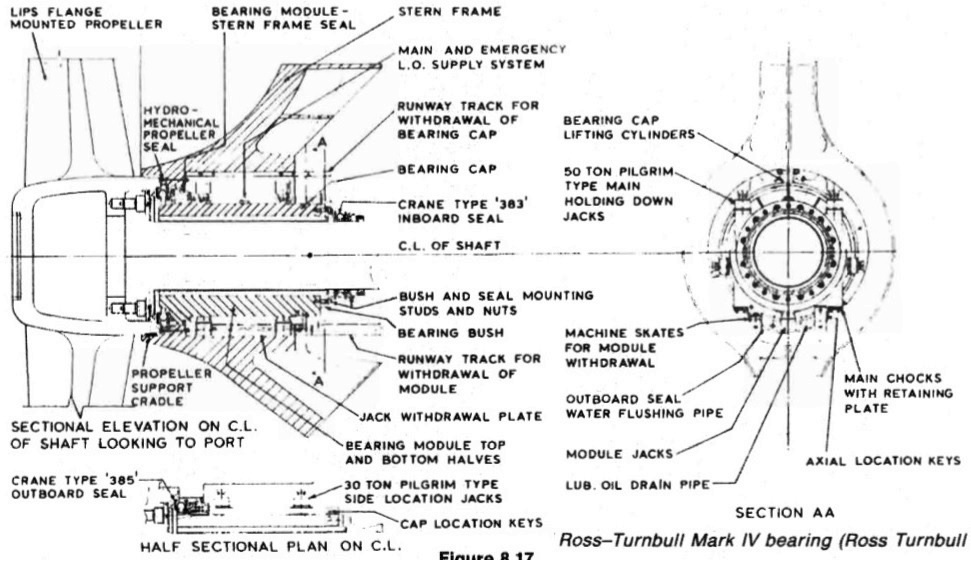
Figure : The Ross-Turnbull split stern bearing
Figure 8,17 General arrangement of Ross-Turnbull Mark IV bearing (Ross Tumbull Ltd.)
Lip seals
A lip seal assembly (Figure 8.18) consists of a number of nitrile rubber rings of
special cross-section (Figure 8.19) sandwiched between bronze rings. Each individual
rubber lip seal is held in contact with a renewable sleeve fitted to the shaft by
its elasticity and a garter spring. The rings are renewed by cutting and then vulcanizing
the ends in situ. The Simplex stern tube (Figure 8.15) has a forward seal
with two rings and an after seal with three rings.
A larger sketch of the after seal
(Figure 8.18) shows how seals are built up from three basic assemblies namely
the flange, intermediate, and cover rings and these parts can be used for either
seal. It will be noticed that the garter spring holding the sealing ring against the
shaft is located aft of the ring anchoring bulb in the case of both forward sealing
rings.
In the case of the after seal the two outboard sealing rings have their garter
springs located aft of the ring anchoring bulbs while the inboard ring has its
garter spring located inboard of the anchoring bulb. Lip seals will accept
misalignment but a floating ring design was introduced by one manufacturer.
In some instances four or more sealing rings are installed. These are arranged
so that one ring does not normally run on the shaft liner. In the event of leakage
from the working seals, adjustment is made to bring the reserve ring into play,
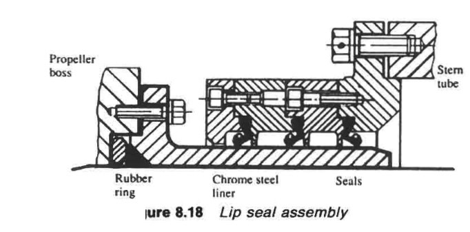
Figure : Lip seal assembly
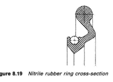
Figure : Nitrile rubber ring cross-section
Radial face seal
An example of a radial face seal, is shown in the general arrangement (Figure
8,20) and a detailed sketch (Figure 8.21) of a Crane seal. One of the principal
features of the design and construction of this type of seal is the split
construction of all component parts. This facilitates installation, and subsequent
inspection and maintenance.
The function of sealing against leakage around the shaft is effected by
sustaining perfect mating contact between the opposing faces of the seal's seat
which rotates with the shaft, and of the main seal unit which is stationary and
clear of the shaft.
This mating contact of the seal faces, which are hydraulically balanced, is
sustained by spring pressure and by the method of flexibly mounting the face
of the main seal unit. The flexible member consists of a tough, but supple,
reinforced bellows. Thus the main seal unit is able to accommodate the effects
of hull deflection and vibration.
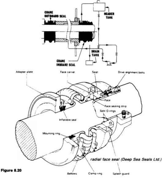
Figure :Example of a radial face seal (Deep Sea Seals Ltd.)
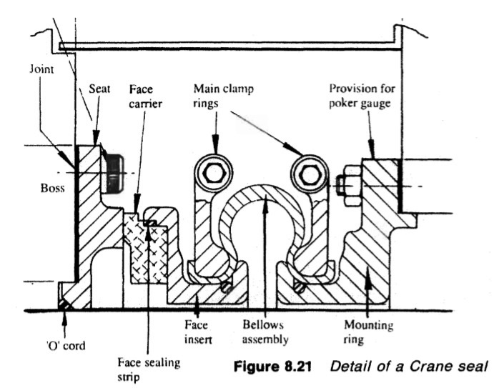
Figure : Detail of a Crane seal
The bellows member is clear of the shaft, and its flexibility therefore cannot
be impaired, as may happen when a flexible member is mounted on the shaft
and hardens, seizes or becomes obstructed by a build-up of solids. The
mechanical design principles also ensure continued sealing under fluctuating
pressure conditions, i.e. changing draught.
An emergency sealing device can be incorporated into the design. The
device, when inflated with air or liquid, forms a tight temporary seal around the
shaft, enabling repairs to be made or a replacement seal fitted when the ship is
afloat, without the shaft being drawn or drydocking being necessary,
Summarized below some of the basic procedure of marine propeller shaft :
- Propeller shaft materials and couplings
The intermediate shafting and the propeller shaft for a fixed propeller are of
solid forged ingot steel and usually with solid forged couplings. Shafts are
machined all over but of a larger diameter and smooth turned in way of the
bearings.
......
- Fixed pitch propeller
The normal method of manufacture for a fixed pitch propeller, is to cast the blades integral with the boss and after inspection and marking, to machine the
tapered bore and faces of the boss before the blades are profiled by hand with reference to datum grooves cut in the surfaces or with an electronically controlled profiling machine.
......
- Controllable pitch propeller
Controllable pitch propellers are normally fitted to a flanged tailshaft as the operating mechanism is housed in the propeller boss. As its name implies, it is possible to alter the pitch of this type of propeller to change ship speed or to adjust to the prevailing resistance conditions.
......
- Propeller thrust block
The main thrust block transfers forward or astern propeller
thrust to the hull and limits axial movement of the shaft. Some axial clearance is essential to
allow formation of an oil film in the wedge shape between the collar and the
thrust pads
......
- Propeller shaft gears and clutches
For medium-speed engine installations in large ships (as opposed to coasters or intermediate sized vessels) reduction gears are needed to permit engines and propellers to run at their best respective speeds. Their use also permits more than one engine to be coupled to the same propeller. Gearboxes are available from manufacturers in standard sizes.
......
- Propeller shaft check
The intention of good alignment is to ensure that bearings are correctly loaded
and that the shaft is not severely stressed. Alignment can be checked with
conventional methods, employing light and targets, laser or measurements
from a taut wire.
......
- Propeller shaft bearings check
The intermediate shafting between the tailshaft and main engine,
gearbox or thrustblock may be supported in plain, tilting pad or roller bearings.
......
- Oil lubricated stern tube
Progress from sea-water to early oil-lubricated stern tubes involved an
exchange of the wooden bearing in its bronze sleeve for a white metal
lined cast iron (or sometimes bronze) bush. Oil retention and exclusion of
sea water necessitated the fitting of an external face type seal.
......
- Water lubricated stern tube
The traditional stern bearing is water-lubricated and consists of a
number of lignum vitae staves held by bronze retaining strips, in a gunmetal
bush. Lignum vitae is a hardwood with good wear characteristics and is
compatible with water.
......
- Stern tube sealing arrangement
There are basically three sealing arrangements used for stern bearings. These are:
Simple stuffing boxes filled with proprietary packing material. Lip seals, in which a number of flexible membranes in contact with the
shaft, prevent the passage of fluid along the shaft.
& Radial face seals, in which a wear-resistant face fitted radially around the
shaft,
......
- Stern tube bearings
To avoid the necessity for drydocking when an examination of stern bearings
amid tailshaft is needed, split stern bearings were developed. A suitable
outboard sealing arrangement and design, permits the two halves of the
bearing to be drawn into the ship, exposing the shaft and the white metal
bearing.
......
Home page||Cooling ||Machinery||Services ||Valves ||Pumps ||Auxiliary Power ||Propeller shaft ||Steering gears ||Ship stabilizers||Refrigeration||Air conditioning ||Deck machinery||Fire protection||Ship design
||Home ||
General Cargo Ship.com provide information on cargo ships various machinery systems -handling procedures, on board safety measures and some basic knowledge of cargo ships that might be useful for people working on board and those who working in the terminal. For any remarks please
Contact us
Copyright © 2010-2016 General Cargo Ship.com All rights reserved.
Terms and conditions of use
Read our privacy policy|| Home page||