
Home page||Propeller shaft ||
Marine propeller shaft materials & various coupling types
Propeller shaft, tail shaft The aftermost section of the propulsion shafting in the stern
tube in single screw ships and in the struts of multiple screw ships to which the propeller
is fitted.
Propulsion shafting constitutes a system of revolving rods that transmit power and motion from
the main drive to the propeller. The shafting is supported by an appropriate number of
bearings.
Shaft materials and couplings:
The intermediate shafting and the propeller shaft for a fixed propeller are of
solid forged ingot steel and usually with solid forged couplings. Shafts are
machined all over but of a larger diameter and smooth turned in way of the
bearings.
The faces of flanged couplings (except where undercut in the centre
area) are also smooth turned, with bolt holes carefully bored and reamered to
give an accurate finish. Torque is transmitted by the friction between flanges
and also through the shanks of the bolts. Each tightened bolt holds the flanges
hard together in the area local to it. A circle of bolts is needed for a good all
round grip. The design of flange couplings can be checked by formulae given in
Lloyds or other classification society regulations.
Coupling bolts
The elongation of a bolt when tightened, causes a reduction in cross sectional
area. The relationship between change in length and the change of cross
sectional area is summarized by Poisson's Ratio. In a clearance bolt, this is not a
problem, but with a normal fitted bolt, positive contact between the accurately
machined bolt and the reamered hole is lost when the bolt is tightened.
An
oversize bolt could of course be used and cooling of the shank probably with
liquid nitrogen - would be necessary to cause contraction and reduction of
cross sectional area before insertion. The effect of low temperature and the
possibility of the steel becoming brittle as the result of the cooling must be
considered.
Shaft coupling bolts are tightened to force the faces of the flanges together,
so that friction between the faces will provide some proportion of the drive.
However, fitted bolt shanks are also designed to take some load. A clearance
bolt could provide the first requirement but not the second. A normal fitted
bolt when tightened and subjected to a reduction in cross section, would also
fail on the second count and probably be damaged by fretting. A tapered bolt
(Figure 8,9) could be used instead of a conventional coupling bolt (Figure 8.8)
to obtain a good fit and the required tightening.
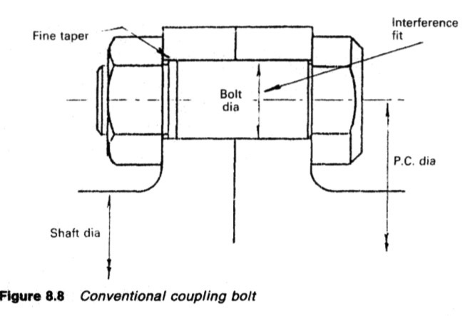
Figure : Conventional coupling bolt
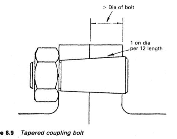
Figure : Tapered coupling bolt
The Pilgrim hydraulic bolt uses the principle embodied in Poisson's Ratio to
provide a calculated and definite fitting force between bolt and hole. The bolt
(Figure 8,10) is hollow and before being fitted is stretched with hydraulic
pressure applied to an inserted rod from a pressure cylinder screwed to the bolt
head.
Stretching makes the bolt diameter small enough for insertion into the
hole, after which the nut is nipped up. Release of hydraulic pressure allows the
bolt to shorten, so that (1) predetermined bolt load is produced and (2)
diametrical re-expansion gives a good fit of the shank in the hole. These bolts,
when used in flange couplings and flange mounted propellers, have the
advantage that they are easily removed for inspection and maintenance.
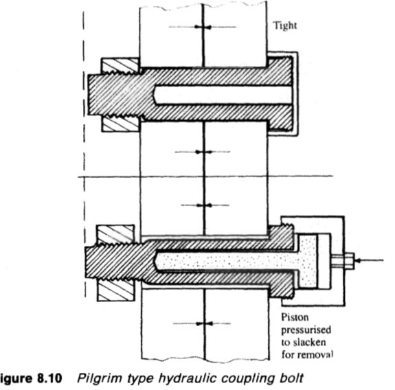
Figure :Pilgrim type hydraulic coupling bolt
Muff coupling
An alternative to the conventional flange couplings for the tailshaft, the muff
coupling allows the shaft to be withdrawn outboard. The SKF coupling (Figure
8.11) consists basically of two steel sleeves. The thin inner sleeve has a bore
slightly larger than the shaft diameter and its outer surface is tapered to match
the taper on the bore of the outer sleeve. The nut and sealing ring close the
annular space at the end of the sleeves.
When the coupling is in position, the outer sleeve is hydraulically driven on
to the tapered inner sleeve. At the same time, oil is injected between the
contact surfaces to separate them and thus overcome the friction between
them. Oil for the operation is supplied by hand pumps; two for the forced
lubrication and another hand or power pump for the driving oil pressure.
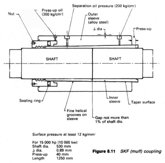
Figure :SKF (muff) coupling
Surface pressure at least 12 kg/mrrv
For 15000 hp (10000 kw)
Shaft dia. 530 mm
Ji dia. 0.89 mm
Press-up 40 mm
Length 1250 mm
When the outer sleeve has been driven on to a predetermined position, the
forced lubrication pressure is released and drained. Oil pressure is maintained in
the hydraulic space until the oil between the sleeves drains and normal friction
is restored. After disconnecting hoses, plugs are fitted and rust preventive
applied to protect exposed seatings. A sealing strip is pressed into the groove
between the end of the sleeve and the nut.
The grip of the coupling is checked by measuring the diameter of the outer
sleeve before and after tightening. The diameter increase should agree with the
figure stamped on the sleeve.
To disconnect the coupling, oil pressure is brought to a set pressure in the
hydraulic space. Then with the shafts supported, oil is forced between the
sleeves. The outer sleeve slides off the inner at a rate controlled by release of
the hydraulic oil pressure.
Summarized below some of the basic procedure of marine propeller shaft :
- Propeller shaft materials and couplings
The intermediate shafting and the propeller shaft for a fixed propeller are of
solid forged ingot steel and usually with solid forged couplings. Shafts are
machined all over but of a larger diameter and smooth turned in way of the
bearings.
......
- Fixed pitch propeller
The normal method of manufacture for a fixed pitch propeller, is to cast the blades integral with the boss and after inspection and marking, to machine the
tapered bore and faces of the boss before the blades are profiled by hand with reference to datum grooves cut in the surfaces or with an electronically controlled profiling machine.
......
- Controllable pitch propeller
Controllable pitch propellers are normally fitted to a flanged tailshaft as the operating mechanism is housed in the propeller boss. As its name implies, it is possible to alter the pitch of this type of propeller to change ship speed or to adjust to the prevailing resistance conditions.
......
- Propeller thrust block
The main thrust block transfers forward or astern propeller
thrust to the hull and limits axial movement of the shaft. Some axial clearance is essential to
allow formation of an oil film in the wedge shape between the collar and the
thrust pads
......
- Propeller shaft gears and clutches
For medium-speed engine installations in large ships (as opposed to coasters or intermediate sized vessels) reduction gears are needed to permit engines and propellers to run at their best respective speeds. Their use also permits more than one engine to be coupled to the same propeller. Gearboxes are available from manufacturers in standard sizes.
......
- Propeller shaft check
The intention of good alignment is to ensure that bearings are correctly loaded
and that the shaft is not severely stressed. Alignment can be checked with
conventional methods, employing light and targets, laser or measurements
from a taut wire.
......
- Propeller shaft bearings check
The intermediate shafting between the tailshaft and main engine,
gearbox or thrustblock may be supported in plain, tilting pad or roller bearings.
......
- Oil lubricated stern tube
Progress from sea-water to early oil-lubricated stern tubes involved an
exchange of the wooden bearing in its bronze sleeve for a white metal
lined cast iron (or sometimes bronze) bush. Oil retention and exclusion of
sea water necessitated the fitting of an external face type seal.
......
- Water lubricated stern tube
The traditional stern bearing is water-lubricated and consists of a
number of lignum vitae staves held by bronze retaining strips, in a gunmetal
bush. Lignum vitae is a hardwood with good wear characteristics and is
compatible with water.
......
- Stern tube sealing arrangement
There are basically three sealing arrangements used for stern bearings. These are:
Simple stuffing boxes filled with proprietary packing material. Lip seals, in which a number of flexible membranes in contact with the
shaft, prevent the passage of fluid along the shaft.
& Radial face seals, in which a wear-resistant face fitted radially around the
shaft,
......
- Stern tube bearings
To avoid the necessity for drydocking when an examination of stern bearings
amid tailshaft is needed, split stern bearings were developed. A suitable
outboard sealing arrangement and design, permits the two halves of the
bearing to be drawn into the ship, exposing the shaft and the white metal
bearing.
......
Home page||Cooling ||Machinery||Services ||Valves ||Pumps ||Auxiliary Power ||Propeller shaft ||Steering gears ||Ship stabilizers||Refrigeration||Air conditioning ||Deck machinery||Fire protection||Ship design
||Home ||
General Cargo Ship.com provide information on cargo ships various machinery systems -handling procedures, on board safety measures and some basic knowledge of cargo ships that might be useful for people working on board and those who working in the terminal. For any remarks please
Contact us
Copyright © 2010-2016 General Cargo Ship.com All rights reserved.
Terms and conditions of use
Read our privacy policy|| Home page||