
Home page||Propeller shaft ||
Marine propeller shaft -
Thrust blocks arrangement
Thrust blocks: The main thrust block transfers forward or astern propeller
thrust to the hull and limits axial movement of the shaft. Some axial clearance is essential to
allow formation of an oil film in the wedge shape between the collar and the
thrust pads (Figure 8.6). This clearance is also needed to allow for expansion as
parts warm up to operating temperature. The actual clearance required,
depends on dimensions of pads, speed, thrust load and the type of oil
employed. High bearing temperature, power loss and failure can result if axial
clearance is too small.
A larger than necessary clearance will not cause harm to the thrust bearing
pads, but axial movement of the shaft must be limited for the protection of
main machinery.
The accepted method of checking thrust clearance, involves jacking the shaft
axially to the end of its travel in one direction and then back to the limit of
travel in the other. Total movement of the thrust shaft (about 1 mm being
typical) is registered on a dial gauge. Feelers can be used as an alternative,
between thrust ring and casing. Use of feelers in the thrust pad/collar gap is
likely to cause damage and may give a false reading.
Thrust block position
The siting of the main thrust block close to the propulsion machinery, reduces
any problems due to differential expansion of the shaft and the hull. The low
hull temperature of midship engined refrigerated cargo ships, caused a
contraction relative to the shaft of perhaps 20mm (|"). Variations can be
caused by changes in water temperature or heating of fuel tanks.
Other
problems associated with the stern tube end of the shafting system include
whirl of the tailshaft, relative movement of the hull and misalignment due to
droop from propeller weight. Some thrusts are housed in the after end of large
slow speed diesels or against gear boxes. Deformation produced by the thrust
load, can cause misalignment problems, unless suitable stiffening is employed
(particularly with an end of gearbox installation).
Thrust block support
The substantial double bottom structure under the main propulsion machinery,
provides an ideal foundation for the thrust block and a further reason for siting
it close to the engine. The upright thrust block and any supporting stool, must
have adequate strength to withstand the effect of loading which tends to cause
a forward tilt. This results in lift of the aft journal of the block (unless not fitted)
and misalignment of the shaft.
Axial vibration of the shaft system, caused by slackening of the propeller
blade load as it turns in the sternframe or by the splay of diesel engine
crankwebs, is normally damped by the thrustblock. Serious vibration problems
have sometimes caused thrust block rock, panting of the tank top and structural
damage.
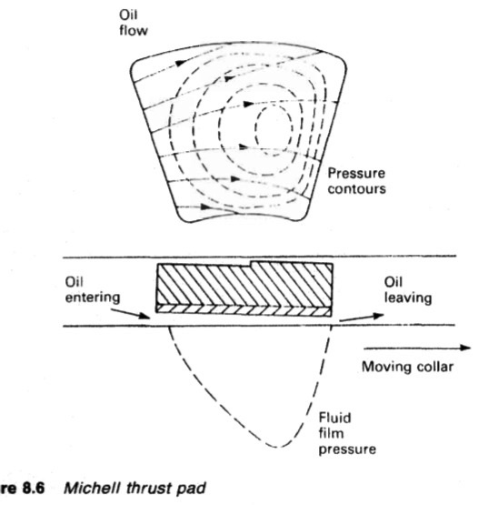
Figure : Michell thrust pad
Thrust pads
The pivot position of thrust pads may be central or offset. Offset pads are
interchangeable in thrust blocks for direct reversing engines, where the
direction of load and rotation changes. Offset pads for non-reversing engine
and controllable pitch propeller installations are not interchangeable. Two sets
are required. Pads with a central pivot position are interchangeable.
Some
modern thrust blocks are fitted with circular pads (Figure 8.7) instead of those
with the familiar kidney shape. A comparison of the pressure contours on the
conventional kidney shaped pads and the circular type shows why the latter
are effective.
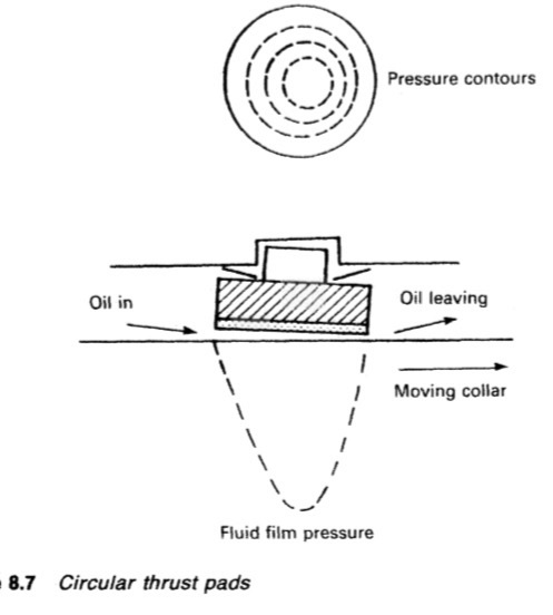
Figure : Circular thrust pads
Summarized below some of the basic procedure of marine propeller shaft :
- Propeller shaft materials and couplings
The intermediate shafting and the propeller shaft for a fixed propeller are of
solid forged ingot steel and usually with solid forged couplings. Shafts are
machined all over but of a larger diameter and smooth turned in way of the
bearings.
......
- Fixed pitch propeller
The normal method of manufacture for a fixed pitch propeller, is to cast the blades integral with the boss and after inspection and marking, to machine the
tapered bore and faces of the boss before the blades are profiled by hand with reference to datum grooves cut in the surfaces or with an electronically controlled profiling machine.
......
- Controllable pitch propeller
Controllable pitch propellers are normally fitted to a flanged tailshaft as the operating mechanism is housed in the propeller boss. As its name implies, it is possible to alter the pitch of this type of propeller to change ship speed or to adjust to the prevailing resistance conditions.
......
- Propeller thrust block
The main thrust block transfers forward or astern propeller
thrust to the hull and limits axial movement of the shaft. Some axial clearance is essential to
allow formation of an oil film in the wedge shape between the collar and the
thrust pads
......
- Propeller shaft gears and clutches
For medium-speed engine installations in large ships (as opposed to coasters or intermediate sized vessels) reduction gears are needed to permit engines and propellers to run at their best respective speeds. Their use also permits more than one engine to be coupled to the same propeller. Gearboxes are available from manufacturers in standard sizes.
......
- Propeller shaft check
The intention of good alignment is to ensure that bearings are correctly loaded
and that the shaft is not severely stressed. Alignment can be checked with
conventional methods, employing light and targets, laser or measurements
from a taut wire.
......
- Propeller shaft bearings check
The intermediate shafting between the tailshaft and main engine,
gearbox or thrustblock may be supported in plain, tilting pad or roller bearings.
......
- Oil lubricated stern tube
Progress from sea-water to early oil-lubricated stern tubes involved an
exchange of the wooden bearing in its bronze sleeve for a white metal
lined cast iron (or sometimes bronze) bush. Oil retention and exclusion of
sea water necessitated the fitting of an external face type seal.
......
- Water lubricated stern tube
The traditional stern bearing is water-lubricated and consists of a
number of lignum vitae staves held by bronze retaining strips, in a gunmetal
bush. Lignum vitae is a hardwood with good wear characteristics and is
compatible with water.
......
- Stern tube sealing arrangement
There are basically three sealing arrangements used for stern bearings. These are:
Simple stuffing boxes filled with proprietary packing material. Lip seals, in which a number of flexible membranes in contact with the
shaft, prevent the passage of fluid along the shaft.
& Radial face seals, in which a wear-resistant face fitted radially around the
shaft,
......
- Stern tube bearings
To avoid the necessity for drydocking when an examination of stern bearings
amid tailshaft is needed, split stern bearings were developed. A suitable
outboard sealing arrangement and design, permits the two halves of the
bearing to be drawn into the ship, exposing the shaft and the white metal
bearing.
......
Home page||Cooling ||Machinery||Services ||Valves ||Pumps ||Auxiliary Power ||Propeller shaft ||Steering gears ||Ship stabilizers||Refrigeration||Air conditioning ||Deck machinery||Fire protection||Ship design
||Home ||
General Cargo Ship.com provide information on cargo ships various machinery systems -handling procedures, on board safety measures and some basic knowledge of cargo ships that might be useful for people working on board and those who working in the terminal. For any remarks please
Contact us
Copyright © 2010-2016 General Cargo Ship.com All rights reserved.
Terms and conditions of use
Read our privacy policy|| Home page||