Home page||Propeller shaft ||
Sea-water lubricated stern tube bearings
Stern tubes:
The propeller shaft (or tailshaft) is supported in a stern tube bearing of one of a
number of designs. The bearing, being at the end of the shaft, is affected by the
overhanging weight of the propeller. The propeller mass pulls the outer end of
the shaft down, so that there is a tendency for edge loading of the stern tube
bearing to occur. The forward part of the propeller shaft is tilted upwards.
Weardown of the bearing aggravates this misalignment and whirl due to
weardown may give additional problems.
Sea-water lubricated stern tube bearings:
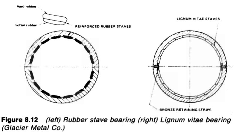
The traditional stern bearing (Figure 8.12) is water-lubricated and consists of a
number of lignum vitae staves held by bronze retaining strips, in a gunmetal
bush. Lignum vitae is a hardwood with good wear characteristics and is
compatible with water. The staves in the lower part of the bearing, are cut and
fitted so that the end grain is vertical to give the longest possible life.
Staves in
the upper part are cut with grain in the axial direction for economy. The staves
are shaped with V or U grooves between them at the surface, to allow access
for water. The grooves also accommodate any debris. As an alternative to
wood, reinforced rubber or Tufhol can be used. Bearing length is equal to four
times shaft diameter.
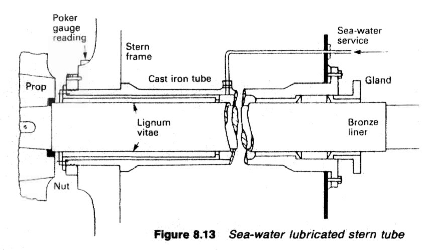
Stern tubes (Figure 8.13) are supported at the after end by the stern frame
boss and at the forward end in the aft peak bulkhead. Their cast iron
construction requires strong support in way of the bearing, from the stem
frame boss.
A steel nut at the outboard end retains the tube in position, with its
collar hard against the sternframe and the bearing section firm within the stem
frame boss. Welded studs hold the forward flange against the aft peak bulkhead.
Sea water, which enters at the after end or from the circulation system to
cool and lubricate, is an electrolyte which will support galvanic corrosion.

Figure 8.12 (left) Rubber stave bearing (right) Lignum vitae bearing
(Glacier Metal Co.)

Figure 8.13 Sea-water lubricated stern tube
Wastage of the vulnerable steel shaft is prevented by a shrunk-on bronze liner
and rubber seal sandwiched between the propeller hub and the liner end. It is
essential that the rubber has freedom to flow when nipped between the hub
and liner.
Excessive weardown of bearing materials due to vibration or whirl, poor
quality of work when rewooding, inferior materials, presence of sand/sediment
in the water or propeller damage, could necessitate early rewooding. The life of
the bearing for vessels with engines aft, and particularly tankers and ore carriers
which spend long periods in ballast, has been short with rewooding being
needed in perhaps eighteen months.
The centre of the stern-tube is connected to a sea-water service line which,
together with ingress of water between the shaft and bush, provides the
cooling and lubrication. A packed gland seals the forward end of the bearing
and is adjusted to permit a slight trickle of water along the shaft and into the
tunnel well where it is regularly removed with the bilge pump. Bearing
clearances are liberal both to accommodate the swelling which occurs when the
staves are immersed in water and to permit the essential flow of water through
the bearing.
A large number of vessels with water-lubricated bearings are still in service
and they continue to be installed.
Inspection of sea-water lubricated stern tubes and tailshaft
During drydock inspection, bearing weardown is measured by poker gauge or
by inserting a wedge between the shaft and bearing from the outside. The
permissible wear is in the region of 9—12 mm on large diameter shafts.
The examination of the type of tailshaft described above requires removal of
the propeller and inward withdrawal of the propeller shaft. The operation calls
for the erection of staging, use of a large, suspended ram or tup for the spanner
to slacken the nut and wedges to start the propeller. The nut remains on the
thread after being slackened for safety reasons.
Accidents have been caused by
the sudden loosening of propellers with no nut in place to act as a stop. Timber
between the aft peak bulkhead and the flange at the forward end of the tailshaft,
supports the shaft against the action of the wedges. The examination when a
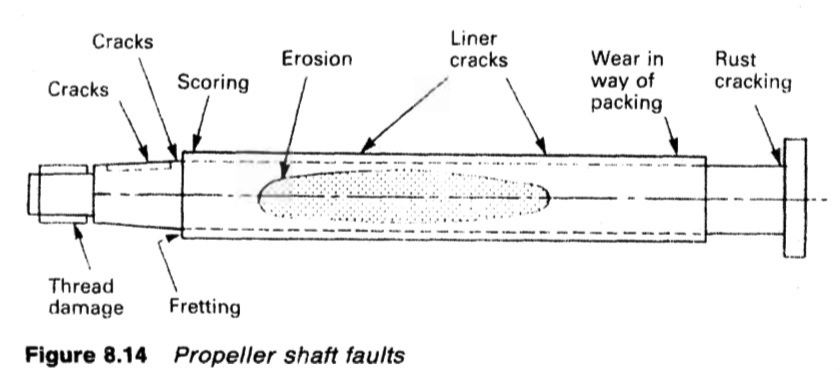
tailshaft has operated in a sea-water lubricated bearing and where the propeller
Is keyed, may reveal (Figure 8.14) a number of defects. There is a potential for
cracks in the keyway area but the likelihood of these occurring has been
reduced by the employment of sled type keys, radiused corners within the
keyway and spooning at the forward end.

Figure 8.14 Propeller shaft faults
A plain keyway milled in a shaft taper, is a weakening factor which allows
deformation of the surface when push up is applied to the propeller and where
there is any transmission of torque from the shaft via the key to the propeller
hub. Torque causes a deformation which tends to open the keyway.
The rubber seal sandwiched by the propeller hub and protective bronze
liner, prevents ingress of sea water which would act as an electrolyte to
promote galvanic corrosion of the exposed part of the shaft.
A defective seal
permits corrosion and wastage. Fretting of the steel shaft tends to occur
beneath the forward end of the propeller hub or under the after end of the liner.
Any pitting or marking of the shaft surface in the area (or notch) between the
propeller hub and the bronze liner can initiate a fatigue or corrosion fatigue
crack in this vulnerable area. (Shaft droop from the overhanging weight of the
propeller, stretches the upper surface and compresses the lower, to produce
alternating stress when the shaft is rotating. The imposed alternating effect
likely to cause fatigue, is of a low frequency and high stress.)
The shrunk-on bronze liner, fitted to protect the steel shaft against black
corrosion may itself be damaged by working conditions. Shaft whirl can lead to
patches marked by cavitation erosion, scoring occurs due to the stern gland
packing and liner cracking has sometimes penetrated through to cause
corrosion cracking in the shaft.
Summarized below some of the basic procedure of marine propeller shaft :
- Propeller shaft materials and couplings
The intermediate shafting and the propeller shaft for a fixed propeller are of
solid forged ingot steel and usually with solid forged couplings. Shafts are
machined all over but of a larger diameter and smooth turned in way of the
bearings.
......
- Fixed pitch propeller
The normal method of manufacture for a fixed pitch propeller, is to cast the blades integral with the boss and after inspection and marking, to machine the
tapered bore and faces of the boss before the blades are profiled by hand with reference to datum grooves cut in the surfaces or with an electronically controlled profiling machine.
......
- Controllable pitch propeller
Controllable pitch propellers are normally fitted to a flanged tailshaft as the operating mechanism is housed in the propeller boss. As its name implies, it is possible to alter the pitch of this type of propeller to change ship speed or to adjust to the prevailing resistance conditions.
......
- Propeller thrust block
The main thrust block transfers forward or astern propeller
thrust to the hull and limits axial movement of the shaft. Some axial clearance is essential to
allow formation of an oil film in the wedge shape between the collar and the
thrust pads
......
- Propeller shaft gears and clutches
For medium-speed engine installations in large ships (as opposed to coasters or intermediate sized vessels) reduction gears are needed to permit engines and propellers to run at their best respective speeds. Their use also permits more than one engine to be coupled to the same propeller. Gearboxes are available from manufacturers in standard sizes.
......
- Propeller shaft check
The intention of good alignment is to ensure that bearings are correctly loaded
and that the shaft is not severely stressed. Alignment can be checked with
conventional methods, employing light and targets, laser or measurements
from a taut wire.
......
- Propeller shaft bearings check
The intermediate shafting between the tailshaft and main engine,
gearbox or thrustblock may be supported in plain, tilting pad or roller bearings.
......
- Oil lubricated stern tube
Progress from sea-water to early oil-lubricated stern tubes involved an
exchange of the wooden bearing in its bronze sleeve for a white metal
lined cast iron (or sometimes bronze) bush. Oil retention and exclusion of
sea water necessitated the fitting of an external face type seal.
......
- Water lubricated stern tube
The traditional stern bearing is water-lubricated and consists of a
number of lignum vitae staves held by bronze retaining strips, in a gunmetal
bush. Lignum vitae is a hardwood with good wear characteristics and is
compatible with water.
......
- Stern tube sealing arrangement
There are basically three sealing arrangements used for stern bearings. These are:
Simple stuffing boxes filled with proprietary packing material. Lip seals, in which a number of flexible membranes in contact with the
shaft, prevent the passage of fluid along the shaft.
& Radial face seals, in which a wear-resistant face fitted radially around the
shaft,
......
- Stern tube bearings
To avoid the necessity for drydocking when an examination of stern bearings
amid tailshaft is needed, split stern bearings were developed. A suitable
outboard sealing arrangement and design, permits the two halves of the
bearing to be drawn into the ship, exposing the shaft and the white metal
bearing.
......
Home page||Cooling ||Machinery||Services ||Valves ||Pumps ||Auxiliary Power ||Propeller shaft ||Steering gears ||Ship stabilizers||Refrigeration||Air conditioning ||Deck machinery||Fire protection||Ship design
||Home ||
General Cargo Ship.com provide information on cargo ships various machinery systems -handling procedures, on board safety measures and some basic knowledge of cargo ships that might be useful for people working on board and those who working in the terminal. For any remarks please
Contact us
Copyright © 2010-2016 General Cargo Ship.com All rights reserved.
Terms and conditions of use
Read our privacy policy|| Home page||


