
Home page||Propeller shaft ||
Propeller Shaft bearings - various type
Propeller shaft, tail shaft – The aftermost section of the propulsion shafting in the stern
tube in single screw ships and in the struts of multiple screw ships to which the propeller
is fitted.
Propulsion shafting constitutes a system of revolving rods that transmit power and motion from
the main drive to the propeller. The shafting is supported by an appropriate number of
bearings.
Shaft bearings : The intermediate shafting (Figure 8.2) between the tailshaft and main engine,
gearbox or thrustblock may be supported in plain, tilting pad or roller bearings.
The two former types usually have individual oil sumps, the oil being
circulated by a collar and scraper device; roller bearings are grease lubricated.
The individual oil sumps usually have cooling water coils or a simple cooling
water chamber fitted. Cooling water is provided from a service main connected
to the sea-water circulating system. The cooling water passes directly overboard.
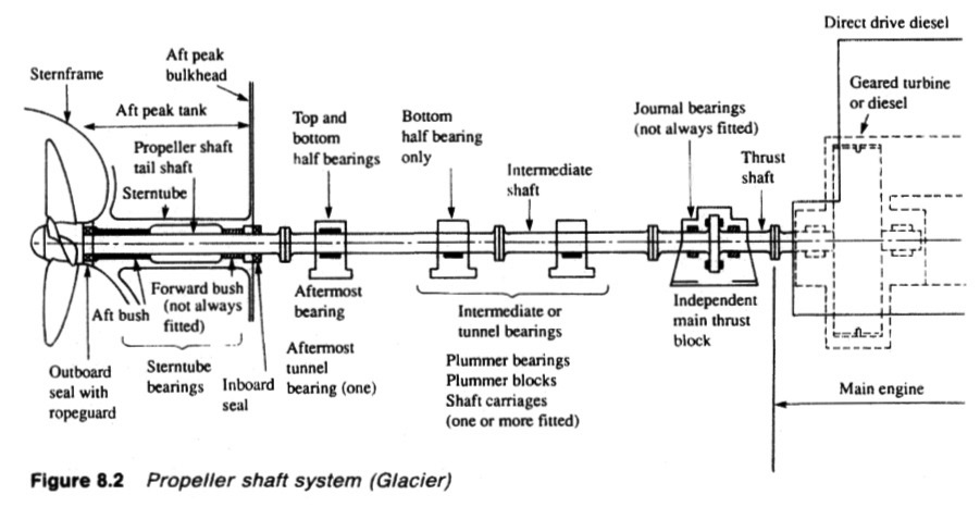
Figure : Propeller shaft system
Usually for plain and tilting pad bearings, only a bottom bearing half is
provided, the top acting purely as a cover. The aftermost plumber block
however, always has a full bearing. This bearing and any bearing in the forward
end of the stern tube, may be subject to negative loading.
Plain bearings
Any oil between a static shaft and plain journal bearing in which it rests, tends
to be squeezed out so that there is metal to metal contact. At the start of the
rotation the journal is inclined to roll up the bearing surface against the
direction of rotation until friction slip occurs. Then, provided there is oil in the
clearance space, this will cling to the moving surface and be dragged between
the shaft and the bearing.
Shaft rotation, as it speeds up, continues to carry oil
to the shaft underside so developing a film with sufficient pressure to hold the
shaft clear of the bearing. The pressure build-up is related to speed of rotation,
Thus oil delivered as the shaft turns at normal speed, will form a layer or film,
separating shaft and bearing, and so prevent direct wear of metal to metal.
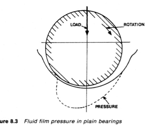
Figure : Fluid film pressure in plain bearing
Pressure generated in the oil film, is most effective over about one third of the
bearing area (Figure 8.3) because of oil loss at the bearing ends and
peripherally. Load is supported and transmitted to the journal, mainly by the
area where the film is generated.
Tilting pad bearings
Replacement of the ineffective side portions of the journal by pads capable of
carrying load will considerably increase its capacity. Tilting pads based on
those developed by Michell for thrust blocks (Figure 8.4a) are used for the
purpose. Each pad tilts as oil is delivered to it, so that a wedge of oil is formed.
The three pressure wedges give a larger total support area than that obtained
with a plain bearing. The arrangement of pads in a bearing is shown in Figure
8.4b.
The tilt of the pads automatically adjusts to suit load, speed and oil viscosity.
The wedge of oil gives a greater separation between shaft and bearing than
does the oil film in a plain journal. The enhanced load capacity of a tilting pad
design, permits the use of shorter length bearings or fewer bearings.
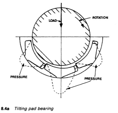
Figure : Tilting pad bearing
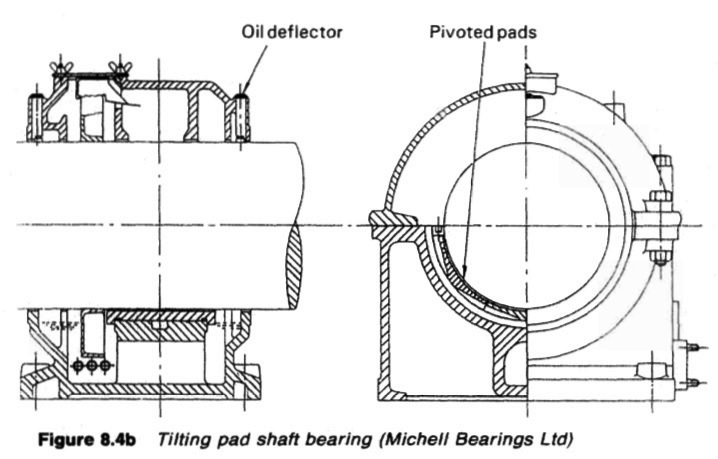
Figure :Tilting pad shaft bearing (Michell Bearings Ltd)
Roller bearings
Roller bearings (Figure 8.5) are supplied in sizes to suit shafts up to the largest
diameter. Flange couplings dictate that roller bearing races must be in two parts
for fitting.
The section of the shaft where the split roller bearing is to be fitted, must be
machined very accurately and with good finish. The two halves of the inner
and outer races are fitted and held with clamping rings.
Adequate speed for build-up of fluid film pressure is vital for journal
bearings. At low speeds there may be metal to metal contact with wear and
damage. Friction at low rotational speeds, is high. Roller bearings are not
dependent on speed for effective lubrication. Friction is low at all speeds. This
makes them suitable for steam turbine installations and in ships where slow
steaming may be necessary. Roller bearings, where fitted, are grease-lubricated.
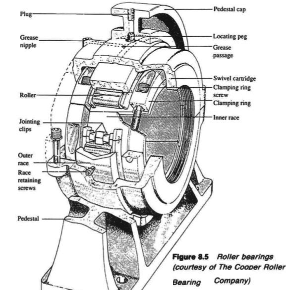
Figure : Roller bearings (courtesy of The Cooper Roller Bearing
Company)
Summarized below some of the basic procedure of marine propeller shaft :
- Propeller shaft materials and couplings
The intermediate shafting and the propeller shaft for a fixed propeller are of
solid forged ingot steel and usually with solid forged couplings. Shafts are
machined all over but of a larger diameter and smooth turned in way of the
bearings.
......
- Fixed pitch propeller
The normal method of manufacture for a fixed pitch propeller, is to cast the blades integral with the boss and after inspection and marking, to machine the
tapered bore and faces of the boss before the blades are profiled by hand with reference to datum grooves cut in the surfaces or with an electronically controlled profiling machine.
......
- Controllable pitch propeller
Controllable pitch propellers are normally fitted to a flanged tailshaft as the operating mechanism is housed in the propeller boss. As its name implies, it is possible to alter the pitch of this type of propeller to change ship speed or to adjust to the prevailing resistance conditions.
......
- Propeller thrust block
The main thrust block transfers forward or astern propeller
thrust to the hull and limits axial movement of the shaft. Some axial clearance is essential to
allow formation of an oil film in the wedge shape between the collar and the
thrust pads
......
- Propeller shaft gears and clutches
For medium-speed engine installations in large ships (as opposed to coasters or intermediate sized vessels) reduction gears are needed to permit engines and propellers to run at their best respective speeds. Their use also permits more than one engine to be coupled to the same propeller. Gearboxes are available from manufacturers in standard sizes.
......
- Propeller shaft check
The intention of good alignment is to ensure that bearings are correctly loaded
and that the shaft is not severely stressed. Alignment can be checked with
conventional methods, employing light and targets, laser or measurements
from a taut wire.
......
- Propeller shaft bearings check
The intermediate shafting between the tailshaft and main engine,
gearbox or thrustblock may be supported in plain, tilting pad or roller bearings.
......
- Oil lubricated stern tube
Progress from sea-water to early oil-lubricated stern tubes involved an
exchange of the wooden bearing in its bronze sleeve for a white metal
lined cast iron (or sometimes bronze) bush. Oil retention and exclusion of
sea water necessitated the fitting of an external face type seal.
......
- Water lubricated stern tube
The traditional stern bearing is water-lubricated and consists of a
number of lignum vitae staves held by bronze retaining strips, in a gunmetal
bush. Lignum vitae is a hardwood with good wear characteristics and is
compatible with water.
......
- Stern tube sealing arrangement
There are basically three sealing arrangements used for stern bearings. These are:
Simple stuffing boxes filled with proprietary packing material. Lip seals, in which a number of flexible membranes in contact with the
shaft, prevent the passage of fluid along the shaft.
& Radial face seals, in which a wear-resistant face fitted radially around the
shaft,
......
- Stern tube bearings
To avoid the necessity for drydocking when an examination of stern bearings
amid tailshaft is needed, split stern bearings were developed. A suitable
outboard sealing arrangement and design, permits the two halves of the
bearing to be drawn into the ship, exposing the shaft and the white metal
bearing.
......
Home page||Cooling ||Machinery||Services ||Valves ||Pumps ||Auxiliary Power ||Propeller shaft ||Steering gears ||Ship stabilizers||Refrigeration||Air conditioning ||Deck machinery||Fire protection||Ship design
||Home ||
General Cargo Ship.com provide information on cargo ships various machinery systems -handling procedures, on board safety measures and some basic knowledge of cargo ships that might be useful for people working on board and those who working in the terminal. For any remarks please
Contact us
Copyright © 2010-2016 General Cargo Ship.com All rights reserved.
Terms and conditions of use
Read our privacy policy|| Home page||


