
Home page||Marine Pumps ||
General pumping system characteristsics for cargo ships
A pump divides its pipe system into two distinct parts, each with different
characteristics. These are the suction and discharge sides. On the suction side
the drop in pressure that can be produced by a pump is limited to that of an
almost perfect vacuum. On the discharge side there is theoretically, no limit to
the height through which a liquid can be raised.
Suction conditions
If a liquid to be pumped is in a tank which is open to atmosphere and it is also at
a height above the pump then the liquid will flow into the pump
because of its head and due to the effect of atmospheric pressure on its surface.
The pump in this case only adds to the energy of the system.
When an open tank containing the liquid to be transferred is at a lower level
than the pump, the energy required to bring the liquid to the pump, is provided
by atmospheric pressure on its surface but the pump must create the drop in
pressure which makes the atmospheric pressure effective.
A discussion of the relevant features of the suction side of a pumping system
must include not only the height of the liquid surface above or below the pump
and the effect of atmospheric pressure, but also the effect of a vacuum or zero
pressure on the liquid surface, vapour pressure and the characteristics of the
suction pipe. Liquid flow through a pipe is impeded by friction over its length,
by valves or other restrictions and by changes of direction.
Discharge conditions
Some of the energy fed into the pump will be dissipated as heat due to
mechanical inefficiencies. The remainder will be converted into pressure rise
and fluid velocity. Some of the pressure head generated will be lost in
overcoming the friction of the discharge pipe , some in the static head of the
pipe system , and some in the pressure head acting on the free surface at the
terminal point . There will also be a velocity head loss but, as in the case of
the suction line, for most practical purposes this can be neglected.
Where the head available is small, the suction line, passages and valves are
specially designed and of a large enough area to reduce the suction losses to a
minimum. This increases the cost of the pump and installation and reduces
efficiency, but is unavoidable for duties such as the extraction of condensate
from a condenser where the head available is frequently a matter of millimetres.
Generally speaking, suction heads require to be greater for high speed or
large capacities than for low speed or small capacities. Condensate pumps,
heater drain pumps and feed pumps operating with direct-contact feed heaters,
must be arranged below the water level as the static head of water is the only
force available to cause the water to flow into the pump, because the water and
the steam on the surface are at the same temperature.
Before liquid can flow into a pump, the air or vapour in the suction line must
be evacuated sufficiently to cause the liquid to flow into the suction chamber.
Some pumps (known as self-priming pumps) do this automatically when
they are started. In others special priming devices must be used to withdraw
the air and lower the pressure in the pump sufficiently to cause flow.
Friction losses
The sum of these losses depends upon the sectional area and the internal
condition of the pipes and fittings, the velocity and viscosity of the liquid being
pumped and the friction caused by bends, valves and other fittings. Frictional
resistance to the flow of water varies approximately as the square of the
velocity. Thus, if the frictional resistance of a condenser and system of piping is
equivalent to a head of 5 m when 800 litres/s are passing, the frictional
resistance would rise to 11.25m with 1200 litres/s and to 20m with
1600 litres/s
Drawings or prints are supplied with pumps by the manufacturers, giving
sizes and particulars of flanges, positions of foundation bolts and other
information necessary for the arrangements of pipe connections. These must
be exactly adhered to; it is little use installing a highly efficient pump if the
power is dissipated and increased by the use of unsuitable pipes and fittings or
by poor layout.
Pipe connections
Connecting pipes of the correct bore should be fitted and this is of special
importance for the suction pipe where restriction causes cavitation. Pipe
connections should be as direct as possible, sharp bends and loops such as that
shown in Figure 1 must be avoided. The loop could increase turbulence
and be the location of an air pocket.
A common fault, causing a great deal of trouble, is shown in Figure 2. Here
the suction pipe connected to the pump slopes downwards to the pump, with
the result that an air pocket is formed.
A similar fault is found when reducing pipes are used to connect an oversize
pipe to the pump inlet. The type of reducing pipe shown at A (Figure 3) in
conjunction with a 90° bend, creates an air pocket. Such a pipe is quite
satisfactory on the discharge side of a pump when used to increase the diameter
of the piping. At the suction side the type of reducer shown at B, could be used.
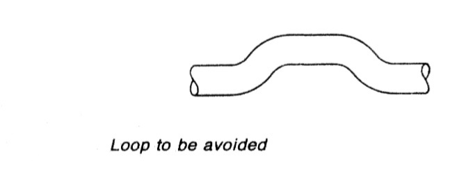
Figure 1: Loop to be avoided
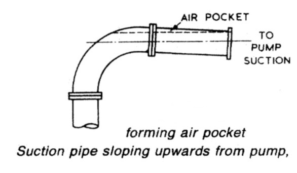
Figure 2: Suction pipe sloping upwards from pump, forming air pocket
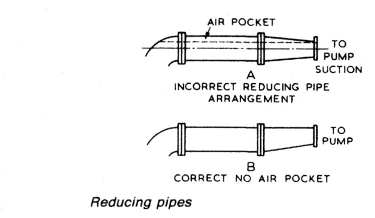
Figure 3:Reducing pipe
Summarized below some of the basic procedure of marine pumps and pumping system onboard :
- Axial flow pumps
An axial flow pump is one in which a screw propeller is used to create an increase in pressure by causing an axial acceleration of liquid within its blades. The incidental rotation imparted to the liquid is converted into straight axial movement by suitably shaped outlet guide vanes.....
- centrifugal pumps
Rotation of a centrifugal pump impeller causes the liquid it contains to move outwards from the centre to beyond the circumference of the impeller. The revolving liquid is impelled by centrifugal effect.....
- Centrifugal pump cavitation
Because of their self-priming ability, positive displacement pumps are widely used for lubricating oil duties. This practice is completely satisfactory in installations where the pump speed is variable but when the pump is driven by a constant speed a.c. motor it is necessary to arrange a bypass which can be closed in to boost flow. ....
- Gear pumps
Diesel engine and gearbox lubrication systems are normally supplied by gear
pumps which are independently driven for large slow speed engines and
stand-by duties but usually shaft driven for medium and high speed engines.
Gear pumps are also used for fuel and oil transfer, boiler combustion systems
and other duties.....
- General pumping system characteristics
A pump divides its pipe system into two distinct parts, each with different
characteristics. These are the suction and discharge sides. On the suction side
the drop in pressure that can be produced by a pump is limited to that of an
almost perfect vacuum. On the discharge side there is theoretically, no limit to
the height through which a liquid can be raised.....
- General purpose pumps
Single entry general purpose pumps are used for salt and fresh water circulating and also for bilge and ballast duties. The impeller is suspended from the shaft with no bottom support. ....
- Lobe pumps
Lobe pumps as manufactured by Stothert and Pitt have inner and outer
elements which rotate in a renewable liner fitted in the pump body. The inner
rotor is eccentric to the outer and is fitted to a shaft located by bearings in the
pump covers....
- Marine pumps construction
Marine pumps are usually installed with the shaft vertical and the motor above the pump. This positions the pump as low as possible for the best NPSH, takes up the least horizontal space and leaves the electric motor safer from gland or other leakage.....
- Pumps erosion
A pump handling liquids which contain abrasives, will suffer erosion on all internal surfaces, including bearings and shaft seals. The sea-water circulating pumps of ships operating in waters that contain large quantities of silt and sand
require frequent renewal of shaft seals or packing, also of shaft sleeves in way of the gland and bearings.....
- Rotary displacement pump
Positive displacement rotary pumps rely on fine clearances between moving
parts for their efficient operation. Excessive wear or erosion of parts, due to
friction contact or the presence of abrasives, is avoided by employing this type
of pump for specialized rather than general duties......
- Screw pumps
Both double-screw pumps, in which the screws are driven in phase by timing
gears , and triple screw pumps , in which the centre
screw is driven and the outer screws idle are used at sea especially for pumping
high viscosity liquids such as oil and some liquid cargoes.....
Home page||Cooling ||Machinery||Services ||Valves ||Pumps ||Auxiliary Power ||Propeller shaft ||Steering gears ||Ship stabilizers||Refrigeration||Air conditioning ||Deck machinery||Fire protection||Ship design
||Home ||
General Cargo Ship.com provide information on cargo ships various machinery systems -handling procedures, on board safety measures and some basic knowledge of cargo ships that might be useful for people working on board and those who working in the terminal. For any remarks please
Contact us
Copyright © 2010-2016 General Cargo Ship.com All rights reserved.
Terms and conditions of use
Read our privacy policy|| Home page||