
Home page||Marine Pumps ||
General purpose pumps - Ship service systems
Single entry general purpose pumps are used for salt and fresh water circulating and also for bilge and ballast duties. The impeller is suspended from the shaft with no bottom support. A neck bush provides lateral location. The eye of the impeller faces downwards, to the suction inlet below the impeller. There are renewable wear rings, usually of aluminium bronze, located at the top and bottom around the collars or boss of the impeller.(Figure 1)
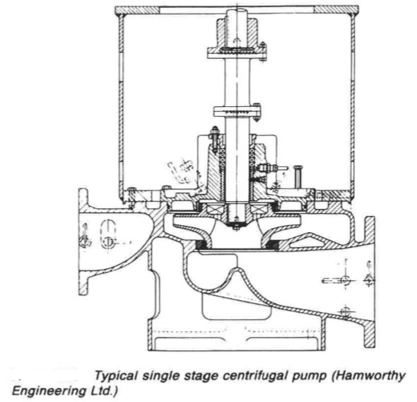
Figure 1: Typical single stage centrifugal pump (Hamworthy Engineering Ltd.)
The clearance between the wear rings and collars is minimal to restrict the flow of liquid from the discharge side. A short circuit flow would reduce efficiency and pressurize the shaft seal. In this design access for maintenance is via the top cover. A distance piece arranged in the shaft, is removed to permit the impeller, shaft and cover, to be lifted out without disturbing the motor or the pipework.
Figure 2 shows a different design of a pump intended for similar duties. The impeller is arranged with its eye uppermost, with the suction branch being elevated. This arrangement is claimed to give better venting to eliminate any possibility of vapour locking. Another significant design difference is that the casing is split vertically so that the impeller and shaft can be removed sideways. The wear rings and neck bush fitted in this design are stepped to abut with the removable part of the casing, to prevent them from turning.
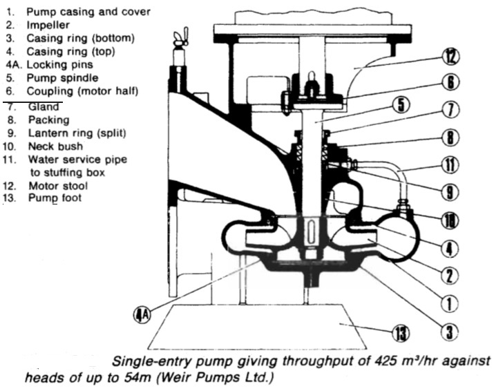
Figure 2: Single entry pump
Where a single entry pump is to be employed to supply a large pressure head, an impeller of a greater diameter (Figure 3) can be used. The model shown also has a vertically split casing and an impeller eye which faces upwards. The added lower guide bush is deemed necessary for the larger diameter impeller.
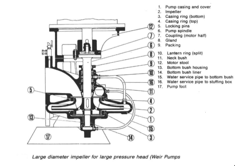
Figure 3: Large diameter impeller for large pressure head
A novel design of single entry pump (Figure 4) was produced for ease of maintenance and adaptability. In this pump the impeller eye faces downwards but the impeller is open-sided, with the bottom of the pump casing effectively shrouding the vanes. This design allows the motor and cover of the pump to be tilted on a hinge so that the operation of a simple screw jack exposes the internal parts. A mechanical seal prevents water leakage or air ingress.
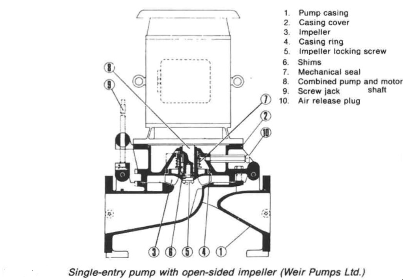
Figure 4: Single entry pump with one sided impeller
This type of pump was designed for a wide range of capacities through simply fitting an impeller of suitable diameter and tip width. As previously stated, the performance of a centrifugal pump is dictated by speed of rotation, the impeller diameter and the area of the flow passage through the impeller (or width). The
first two variables basically control the pressure generated and the last the quantity of liquid delivered.
A similar effect would be produced by using different speeds. Variation of capacity at constant speed and diameter, facilitated by fitting impellers of different widths produces a different type of performance variation. Obviously, by altering impeller diameters and widths, a pump can be tailored to requirements.
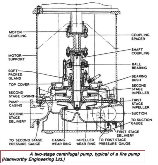
Figure 5: Two stage centrifugal pump
A two-stage pump (Figure 5) may be installed as a fire and general service pump. Because both low and high head are available from the one pump, it can be readily used for a double duty. Lower head is obtained by pumping through the first stage impeller only and a higher head when pumping through both impellers.
Summarized below some of the basic procedure of marine pumps and pumping system onboard :
- Axial flow pumps
An axial flow pump is one in which a screw propeller is used to create an increase in pressure by causing an axial acceleration of liquid within its blades. The incidental rotation imparted to the liquid is converted into straight axial movement by suitably shaped outlet guide vanes.....
- centrifugal pumps
Rotation of a centrifugal pump impeller causes the liquid it contains to move outwards from the centre to beyond the circumference of the impeller. The revolving liquid is impelled by centrifugal effect.....
- Centrifugal pump cavitation
Because of their self-priming ability, positive displacement pumps are widely used for lubricating oil duties. This practice is completely satisfactory in installations where the pump speed is variable but when the pump is driven by a constant speed a.c. motor it is necessary to arrange a bypass which can be closed in to boost flow. ....
- Gear pumps
Diesel engine and gearbox lubrication systems are normally supplied by gear
pumps which are independently driven for large slow speed engines and
stand-by duties but usually shaft driven for medium and high speed engines.
Gear pumps are also used for fuel and oil transfer, boiler combustion systems
and other duties.....
- General pumping system characteristics
A pump divides its pipe system into two distinct parts, each with different
characteristics. These are the suction and discharge sides. On the suction side
the drop in pressure that can be produced by a pump is limited to that of an
almost perfect vacuum. On the discharge side there is theoretically, no limit to
the height through which a liquid can be raised.....
- General purpose pumps
Single entry general purpose pumps are used for salt and fresh water circulating and also for bilge and ballast duties. The impeller is suspended from the shaft with no bottom support. ....
- Lobe pumps
Lobe pumps as manufactured by Stothert and Pitt have inner and outer
elements which rotate in a renewable liner fitted in the pump body. The inner
rotor is eccentric to the outer and is fitted to a shaft located by bearings in the
pump covers....
- Marine pumps construction
Marine pumps are usually installed with the shaft vertical and the motor above the pump. This positions the pump as low as possible for the best NPSH, takes up the least horizontal space and leaves the electric motor safer from gland or other leakage.....
- Pumps erosion
A pump handling liquids which contain abrasives, will suffer erosion on all internal surfaces, including bearings and shaft seals. The sea-water circulating pumps of ships operating in waters that contain large quantities of silt and sand
require frequent renewal of shaft seals or packing, also of shaft sleeves in way of the gland and bearings.....
- Rotary displacement pump
Positive displacement rotary pumps rely on fine clearances between moving
parts for their efficient operation. Excessive wear or erosion of parts, due to
friction contact or the presence of abrasives, is avoided by employing this type
of pump for specialized rather than general duties......
- Screw pumps
Both double-screw pumps, in which the screws are driven in phase by timing
gears , and triple screw pumps , in which the centre
screw is driven and the outer screws idle are used at sea especially for pumping
high viscosity liquids such as oil and some liquid cargoes.....
Home page||Cooling ||Machinery||Services ||Valves ||Pumps ||Auxiliary Power ||Propeller shaft ||Steering gears ||Ship stabilizers||Refrigeration||Air conditioning ||Deck machinery||Fire protection||Ship design
||Home ||
General Cargo Ship.com provide information on cargo ships various machinery systems -handling procedures, on board safety measures and some basic knowledge of cargo ships that might be useful for people working on board and those who working in the terminal. For any remarks please
Contact us
Copyright © 2010-2016 General Cargo Ship.com All rights reserved.
Terms and conditions of use
Read our privacy policy|| Home page||