
Home page||Marine Pumps ||
Marine pumps - Construction and installation
Marine pumps are usually installed with the shaft vertical and the motor above the pump. This positions the pump as low as possible for the best NPSH, takes up the least horizontal space and leaves the electric motor safer from gland or other leakage.
Shaft sealing
It is preferable on vertical pumps to have shaft sealing at the pump upper end only. This permits observation and adjustment of the shaft seal and ensures that the pump does not drain through a leaking gland during idle periods (i.e. the pump will remain free because deposits will not harden).
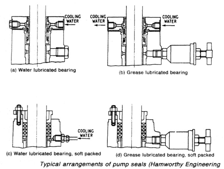
Figure 1: Typical arrangements of pump seals (Hamworthy Engineering Ltd.)
Mechanical seals (Figures 1a and 1b) are spring loaded to hold the sealing faces together. It is important that cooling and lubricating liquid is led
(a) Water lubricated bearing (c) Water lubricated bearing, soft packed (b) Grease lubricated bearing (d) Grease lubricated bearing, soft packed to mechanical seals from the lowest point on the pressure side of the pump, to ensure that some liquid reaches them, even when priming.
Special header tanks have been installed for the seals in some applications. They must not ran dry and care must be taken to prevent ingress of foreign matter. Many mechanical seals incorporate a carbon face and there is a possibility of electrolytic action in the presence of sea water.
Soft packing may be preferred in sea-water pumps, Stuffing box type glands (Figures 1c and 1d) may be packed with soft or metal foil type packing. Pump internal bearings may be lubricated and cooled by the pumped liquid in situations where liquid is always available when the pump is running. Lubricators for the application of grease are fitted in some circumstances. Pumps used for slurries or those for suction dredgers, have external bearings and a nozzle located to exclude solids from the gland area.
Materials
Pumps like pipelines, are used for high or low temperature liquids, those which are corrosive and some that carry abrasive particles. The materials chosen for pump construction must be suitable.
- (a)Pumps for engine cooling water, fresh or potable water: high grade cast iron casings with bronze internals shaft of bronze or stainless steel (EN57. 18 Cr/2Ni) the latter material gives better wear life.
- (b) Sea-water pumps: (these must also handle harbour, river and canal water) may have gunmetal casing with aluminium bronze impeller (BS 1400 AB2 9: 5AI - 5 Fe - 5.5 Ni) - shaft either stainless steel (EN57) for soft packed stuffing boxes or EN58J (18Cr lONi 3 Mo) under mechanical seals or bearings
- (c) Boiler feed pumps: because of the high pressures and temperatures casings are of cast steel - shafts and impellers of stainless steel.
- (d) Cargo pumps: stainless steel casings, impeller and shaft suitable for most chemicals nickel steels for low temperature liquefied gas.
Priming
Pumps may be mounted above the level of the liquid to be pumped even though placed low in the ship. Bilge pumps for this reason, must be self-priming or equipped with a means of priming, to create a vacuum in the suction pipeline.
Ballast and other pumps (which may also be statutory bilge pumps) may need to be self-priming or equipped with a means of priming. Cargo pumps for oil tankers are likely to be arranged for stripping the maximum amount of liquid from tanks.
A centrifugal pump placed above the liquid to be pumped, is not self-priming because it cannot exhaust the air contained in its casing and suction pipe. A displacement pump can and is self-priming. A centrifugal pump must be placed below the level of the liquid to be pumped (when it will flood if valves are opened) or it must be provided with an external device for the removal of air.
Air handling methods
The removal of air from pump suction pipes is usually achieved with a liquid ring primer. This is necessary in order to produce vacuum conditions, so that atmospheric pressure on the surface of the liquid to be pumped will promote flow into and priming of the pump, The liquid ring air pump (Figure 2) consists of a bladed circular rotor, shrouded on the underside, which rotates in an oval casing. Sealing water is drawn into the oval casing through a make-up supply pipe (in older types is was added through a plug).
The water, thrown out to the casing periphery by the turning rotor, whirls around, to form a moving layer against the oval casing. The water seals the rotor blades and also recedes from and re-approaches the rotor boss twice in each revolution. The effect is to produce a series of reciprocating water pistons between the blades. As the water surface moves out from the rotor boss, it provides a suction stroke and, as it moves in, a discharge stroke. The shaped suction and discharge ports, provided above the elliptical core formed by the rotating water, permit air to be drawn in from the main pump suction pipe float chamber and expelled through the discharge ports, to atmosphere.
A continuous supply of sealing water is circulated from the primer reservoir to the whirlpool casing, and discharged with the air back to the reservoir. The air passes to atmosphere through the overflow pipe. This circulation ensures that a full water-ring is maintained and the cooling coil incorporated in the reservoir, limits the temperature rise of the sealing water during long periods of operation. The supply for the cooling coil can be taken from any convenient sea-water connection. About 0.152 litres/s is required at a pressure not exceeding 2 bar.
The air handling capacity of water ring primers is good, with air gulps being quickly cleared and small air leakages being handled without any fall in pump performance. This type of primer, replaced the now obsolete reciprocating pump primers. Eccentric vane primers have good air handling capability but vanes wear and they sometimes jam in the rotor slots. Ejectors are effective if sized correctly but their efficiency is low.
Float chamber
The water ring primer draws air from the pump suction pipe, through a float chamber (Figure 2). The float rises as liquid replaces air and as the level rises well above the pump the impeller and casing are flooded and the float spindle closes off the suction. This ensures that the primer itself is not flooded.
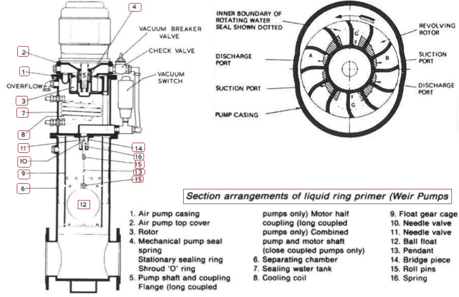
Figure 2 : Section arrangements of liquid ring primer (Weir Pumps Ltd.)
Central priming system
This system may be used when more than four pumps require priming facilities. It gives a large air exhausting reservoir as well as capacity greater than individual pumps can carry. Pump casings can be filled with liquid before starting. The air exhausting units are usually of the liquid ring type. A typical schematic arrangement is shown in Figure 3.
A float chamber arrangement is also used with central primers to prevent flooding of the priming unit.
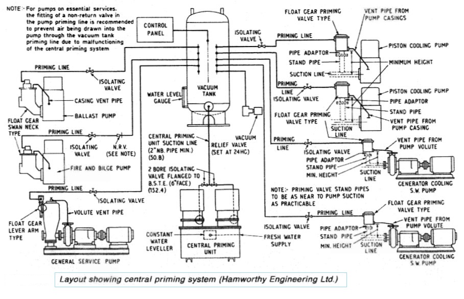
Figure 3: Marine pump central priming system
Summarized below some of the basic procedure of marine pumps and pumping system onboard :
- Axial flow pumps
An axial flow pump is one in which a screw propeller is used to create an increase in pressure by causing an axial acceleration of liquid within its blades. The incidental rotation imparted to the liquid is converted into straight axial movement by suitably shaped outlet guide vanes.....
- centrifugal pumps
Rotation of a centrifugal pump impeller causes the liquid it contains to move outwards from the centre to beyond the circumference of the impeller. The revolving liquid is impelled by centrifugal effect.....
- Centrifugal pump cavitation
Because of their self-priming ability, positive displacement pumps are widely used for lubricating oil duties. This practice is completely satisfactory in installations where the pump speed is variable but when the pump is driven by a constant speed a.c. motor it is necessary to arrange a bypass which can be closed in to boost flow. ....
- Gear pumps
Diesel engine and gearbox lubrication systems are normally supplied by gear
pumps which are independently driven for large slow speed engines and
stand-by duties but usually shaft driven for medium and high speed engines.
Gear pumps are also used for fuel and oil transfer, boiler combustion systems
and other duties.....
- General pumping system characteristics
A pump divides its pipe system into two distinct parts, each with different
characteristics. These are the suction and discharge sides. On the suction side
the drop in pressure that can be produced by a pump is limited to that of an
almost perfect vacuum. On the discharge side there is theoretically, no limit to
the height through which a liquid can be raised.....
- General purpose pumps
Single entry general purpose pumps are used for salt and fresh water circulating and also for bilge and ballast duties. The impeller is suspended from the shaft with no bottom support. ....
- Lobe pumps
Lobe pumps as manufactured by Stothert and Pitt have inner and outer
elements which rotate in a renewable liner fitted in the pump body. The inner
rotor is eccentric to the outer and is fitted to a shaft located by bearings in the
pump covers....
- Marine pumps construction
Marine pumps are usually installed with the shaft vertical and the motor above the pump. This positions the pump as low as possible for the best NPSH, takes up the least horizontal space and leaves the electric motor safer from gland or other leakage.....
- Pumps erosion
A pump handling liquids which contain abrasives, will suffer erosion on all internal surfaces, including bearings and shaft seals. The sea-water circulating pumps of ships operating in waters that contain large quantities of silt and sand
require frequent renewal of shaft seals or packing, also of shaft sleeves in way of the gland and bearings.....
- Rotary displacement pump
Positive displacement rotary pumps rely on fine clearances between moving
parts for their efficient operation. Excessive wear or erosion of parts, due to
friction contact or the presence of abrasives, is avoided by employing this type
of pump for specialized rather than general duties......
- Screw pumps
Both double-screw pumps, in which the screws are driven in phase by timing
gears , and triple screw pumps , in which the centre
screw is driven and the outer screws idle are used at sea especially for pumping
high viscosity liquids such as oil and some liquid cargoes.....
Home page||Cooling ||Machinery||Services ||Valves ||Pumps ||Auxiliary Power ||Propeller shaft ||Steering gears ||Ship stabilizers||Refrigeration||Air conditioning ||Deck machinery||Fire protection||Ship design
||Home ||
General Cargo Ship.com provide information on cargo ships various machinery systems -handling procedures, on board safety measures and some basic knowledge of cargo ships that might be useful for people working on board and those who working in the terminal. For any remarks please
Contact us
Copyright © 2010-2016 General Cargo Ship.com All rights reserved.
Terms and conditions of use
Read our privacy policy|| Home page||